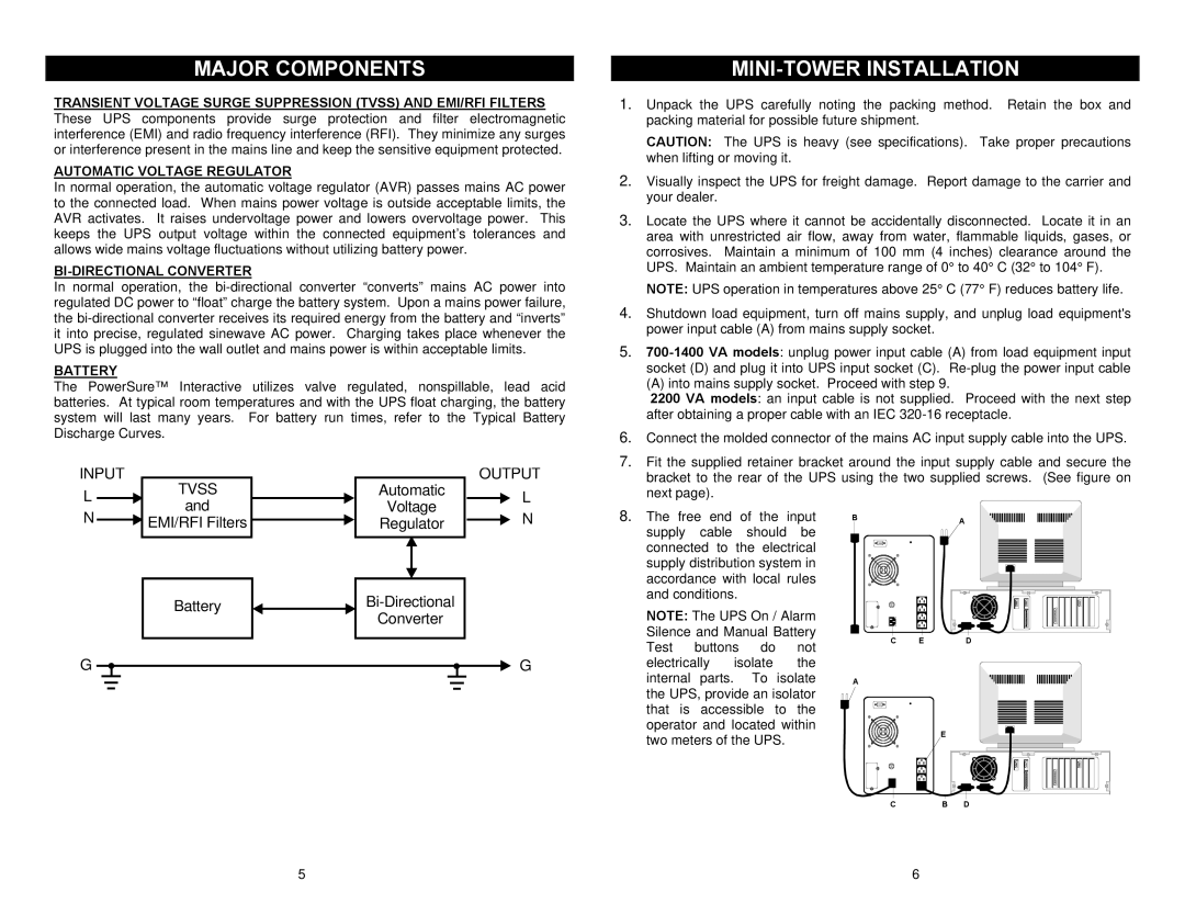
MAJOR COMPONENTS
TRANSIENT VOLTAGE SURGE SUPPRESSION (TVSS) AND EMI/RFI FILTERS
These UPS components provide surge protection and filter electromagnetic interference (EMI) and radio frequency interference (RFI). They minimize any surges or interference present in the mains line and keep the sensitive equipment protected.
AUTOMATIC VOLTAGE REGULATOR
In normal operation, the automatic voltage regulator (AVR) passes mains AC power to the connected load. When mains power voltage is outside acceptable limits, the AVR activates. It raises undervoltage power and lowers overvoltage power. This keeps the UPS output voltage within the connected equipment’s tolerances and allows wide mains voltage fluctuations without utilizing battery power.
BI-DIRECTIONAL CONVERTER
In normal operation, the
BATTERY
The PowerSure™ Interactive utilizes valve regulated, nonspillable, lead acid batteries. At typical room temperatures and with the UPS float charging, the battery system will last many years. For battery run times, refer to the Typical Battery Discharge Curves.
INPUT | TVSS |
| OUTPUT | |
L | Automatic | L | ||
and | Voltage | |||
|
|
MINI-TOWER INSTALLATION
1.Unpack the UPS carefully noting the packing method. Retain the box and packing material for possible future shipment.
CAUTION: The UPS is heavy (see specifications). Take proper precautions when lifting or moving it.
2.Visually inspect the UPS for freight damage. Report damage to the carrier and your dealer.
3.Locate the UPS where it cannot be accidentally disconnected. Locate it in an area with unrestricted air flow, away from water, flammable liquids, gases, or corrosives. Maintain a minimum of 100 mm (4 inches) clearance around the UPS. Maintain an ambient temperature range of 0° to 40° C (32° to 104° F).
NOTE: UPS operation in temperatures above 25° C (77° F) reduces battery life.
4.Shutdown load equipment, turn off mains supply, and unplug load equipment's power input cable (A) from mains supply socket.
5.
(A) into mains supply socket. Proceed with step 9.
2200 VA models: an input cable is not supplied. Proceed with the next step after obtaining a proper cable with an IEC
6.Connect the molded connector of the mains AC input supply cable into the UPS.
7.Fit the supplied retainer bracket around the input supply cable and secure the bracket to the rear of the UPS using the two supplied screws. (See figure on next page).
N | EMI/RFI Filters | Regulator | N |
|
|
Battery |
| |
Converter | ||
|
G ![]() G
G
8.The free end of the input supply cable should be connected to the electrical supply distribution system in accordance with local rules and conditions.
NOTE: The UPS On / Alarm Silence and Manual Battery Test buttons do not
electrically isolate the internal parts. To isolate the UPS, provide an isolator that is accessible to the operator and located within two meters of the UPS.
BA
C ED
A
| E |
|
C | B | D |
5 | 6 |