The wires in the mains lead are colored with the following code:
Green and Yellow = Earth
Blue = Neutral
Brown = Live
As the color of the wires in the mains lead may not correspond with the colored marking identifying the terminals in the plug, proceed as follows:
The green and yellow wire must be connected to the terminal in the plug which is marked with the letter “E” or by the earth symbol, or colored green and yellow.
The blue wire must be connected to the terminal which is marked with the letter “N” or colored black.
The brown wire must be connected to the terminal which is marked with the letter “L” or colored red.
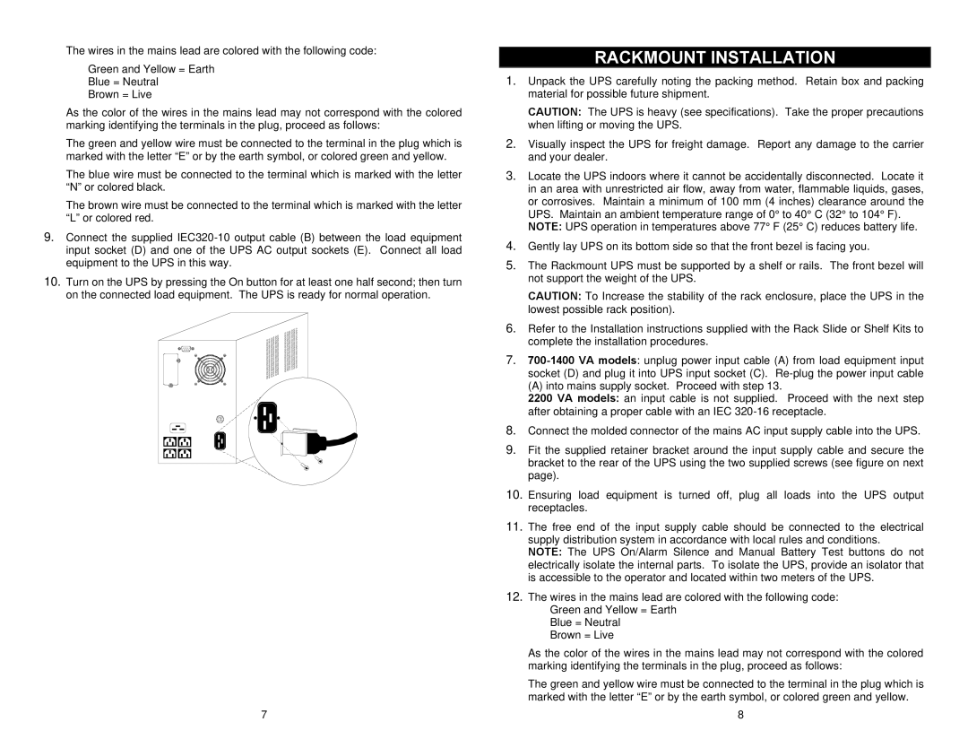
9.Connect the supplied
10.Turn on the UPS by pressing the On button for at least one half second; then turn on the connected load equipment. The UPS is ready for normal operation.
7
RACKMOUNT INSTALLATION
1.Unpack the UPS carefully noting the packing method. Retain box and packing material for possible future shipment.
CAUTION: The UPS is heavy (see specifications). Take the proper precautions when lifting or moving the UPS.
2.Visually inspect the UPS for freight damage. Report any damage to the carrier and your dealer.
3.Locate the UPS indoors where it cannot be accidentally disconnected. Locate it in an area with unrestricted air flow, away from water, flammable liquids, gases, or corrosives. Maintain a minimum of 100 mm (4 inches) clearance around the UPS. Maintain an ambient temperature range of 0° to 40° C (32° to 104° F).
NOTE: UPS operation in temperatures above 77° F (25° C) reduces battery life.
4.Gently lay UPS on its bottom side so that the front bezel is facing you.
5.The Rackmount UPS must be supported by a shelf or rails. The front bezel will not support the weight of the UPS.
CAUTION: To Increase the stability of the rack enclosure, place the UPS in the lowest possible rack position).
6.Refer to the Installation instructions supplied with the Rack Slide or Shelf Kits to complete the installation procedures.
7.
(A) into mains supply socket. Proceed with step 13.
2200 VA models: an input cable is not supplied. Proceed with the next step after obtaining a proper cable with an IEC
8.Connect the molded connector of the mains AC input supply cable into the UPS.
9.Fit the supplied retainer bracket around the input supply cable and secure the bracket to the rear of the UPS using the two supplied screws (see figure on next page).
10.Ensuring load equipment is turned off, plug all loads into the UPS output receptacles.
11.The free end of the input supply cable should be connected to the electrical supply distribution system in accordance with local rules and conditions.
NOTE: The UPS On/Alarm Silence and Manual Battery Test buttons do not electrically isolate the internal parts. To isolate the UPS, provide an isolator that is accessible to the operator and located within two meters of the UPS.
12.The wires in the mains lead are colored with the following code:
Green and Yellow = Earth
Blue = Neutral
Brown = Live
As the color of the wires in the mains lead may not correspond with the colored marking identifying the terminals in the plug, proceed as follows:
The green and yellow wire must be connected to the terminal in the plug which is marked with the letter “E” or by the earth symbol, or colored green and yellow.
8
