Installation
3.8EPO Switch
The Liebert PSI XR is equipped with an Emergency Power Off (EPO) switch. The user must supply a means of interfacing with the EPO circuit to allow disconnecting the UPS input feeder breaker to interrupt all sources of power to the UPS and connected equipment to comply with national and local wiring codes and regulations.
Figure 13 EPO connection for normally open operation
1
2
1 = EPO+
2 = Ground
Short Pin 1 and Pin 2 to enable the EPO function
3.9External Battery Cabinet Installation
Optional Liebert external battery cabinets may be connected to the UPS to provide additional battery run time. External battery cabinets are designed to be placed all on one side of the UPS or stacked beneath the UPS. The batteries have a maximum run time of three hours at full load.
1.Install the external battery cabinet in tower- or
2.Connect the external battery cabinet cable to the rear of the external battery cabinet, then to the rear of the UPS (see Figure 15).
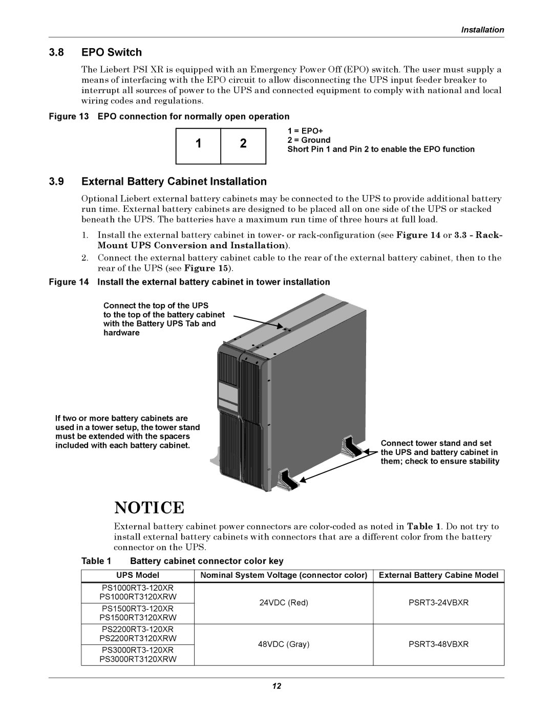
Figure 14 Install the external battery cabinet in tower installation
Connect the top of the UPS
to the top of the battery cabinet with the Battery UPS Tab and hardware
If two or more battery cabinets are used in a tower setup, the tower stand must be extended with the spacers included with each battery cabinet.
Connect tower stand and set ![]() the UPS and battery cabinet in
the UPS and battery cabinet in
them; check to ensure stability
NOTICE
External battery cabinet power connectors are
Table 1 Battery cabinet connector color key
UPS Model | Nominal System Voltage (connector color) | External Battery Cabine Model | |
|
| ||
PS1000RT3120XRW | 24VDC (Red) | ||
|
| ||
PS1500RT3120XRW |
|
| |
|
| ||
PS2200RT3120XRW | 48VDC (Gray) | ||
|
| ||
PS3000RT3120XRW |
|
|
12