PSITM specifications
The Liebert PSITM is an advanced power protection system designed to ensure the reliability and efficiency of critical systems in data centers, industrial applications, and mission-critical environments. As the demand for uninterrupted power supply continues to grow, the Liebert PSI serves as an indispensable asset.One of the main features of the Liebert PSI is its online double-conversion technology. This method guarantees a continuous supply of clean and stable power to connected loads by converting incoming AC power to DC, then back to AC. This process eliminates power disturbances such as voltage sags, surges, and harmonics, ensuring that sensitive equipment operates without interruption.
In addition to its robust power protection capabilities, the Liebert PSI offers scalable solutions to meet varying power requirements. Ranging from 5 kVA to 40 kVA, it can be configured for single or three-phase operation. This flexibility allows businesses to tailor the system to match their specific needs, whether they are expanding data center operations or simply upgrading existing infrastructure.
Another notable characteristic of the Liebert PSI is its energy efficiency. The unit is designed to operate with a high efficiency of up to 94%, which not only reduces operational costs but also minimizes the environmental impact. Moreover, it features an eco-mode that optimizes energy use during non-critical operations without sacrificing reliability.
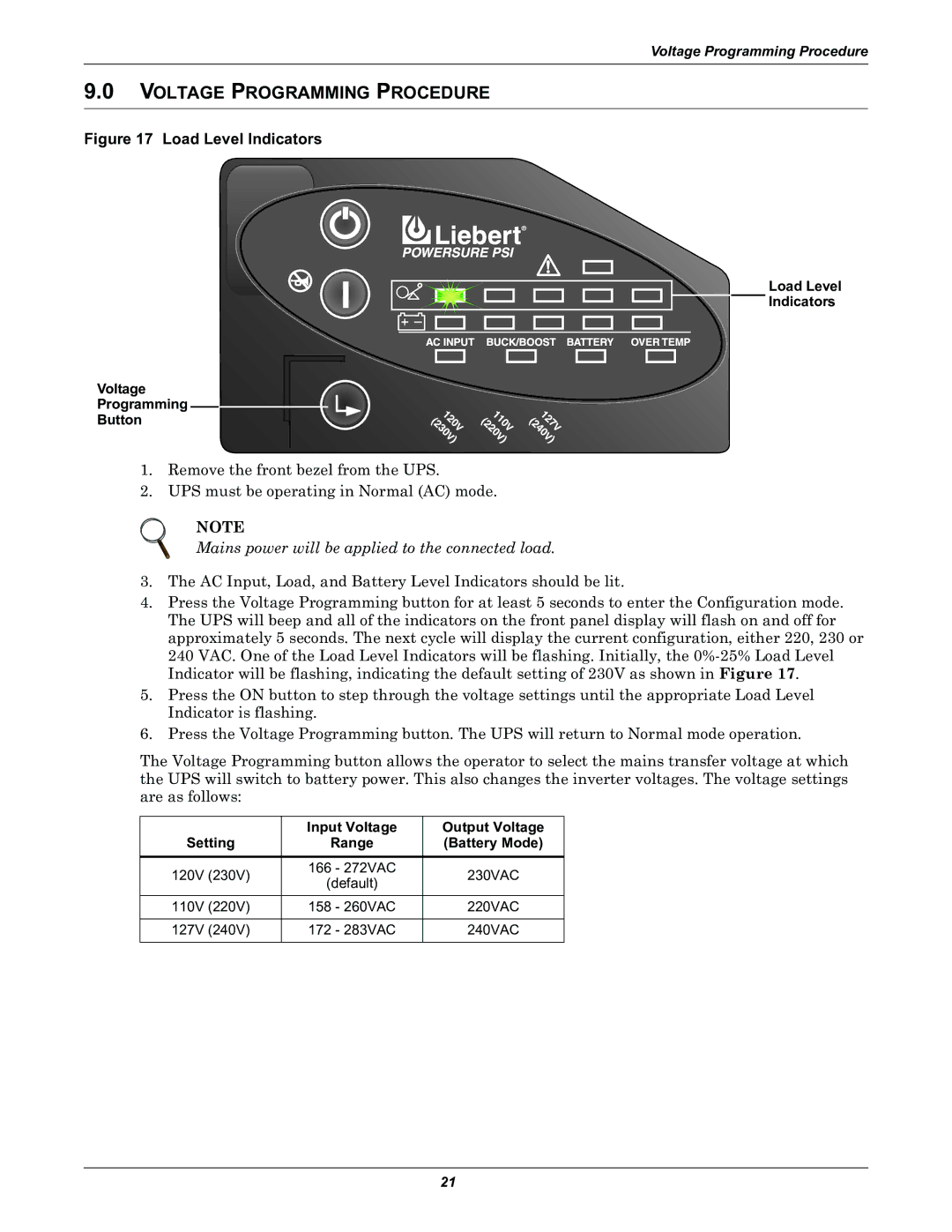
The Liebert PSI is equipped with advanced communication and management capabilities. It includes an intuitive LCD display for real-time monitoring, enabling users to access vital information about the unit's performance and status. Additionally, it supports various communication protocols such as SNMP and Modbus, allowing for seamless integration into existing management systems.
Furthermore, the Liebert PSI is designed with an emphasis on modularity, allowing for easy upgrades and maintenance. This modular approach reduces downtime and enhances serviceability, ensuring that the system remains reliable throughout its lifecycle.
In summary, the Liebert PSITM stands out as a comprehensive power protection solution that combines cutting-edge technology, energy efficiency, and user-friendly features. Its commitment to safeguarding critical systems against power disturbances makes it a vital component in the infrastructure of any modern data center or industrial setting.

