3.5-6 kVA Start-up Checklist

1.Remove POD from box. Set aside the two UPS battery fuses inside the user manual packet for later installation.

Steps 2 – 4 apply to UPS Hardwire Input / Output connections ONLY.

For standard plug connections, skip to step 5.

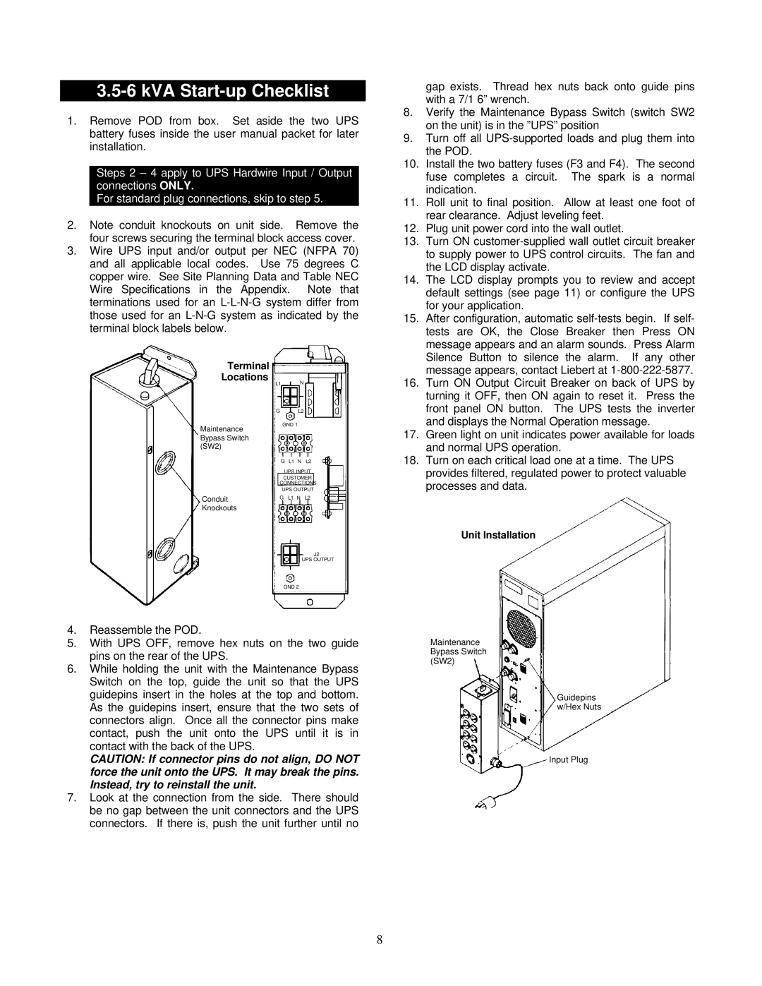
2.Note conduit knockouts on unit side. Remove the four screws securing the terminal block access cover.

3.Wire UPS input and/or output per NEC (NFPA 70) and all applicable local codes. Use 75 degrees C copper wire. See Site Planning Data and Table NEC Wire Specifications in the Appendix. Note that terminations used for an L-L-N-G system differ from those used for an L-N-G system as indicated by the terminal block labels below.

Terminal


Locations

L1

N


G

L2

Maintenance

GND 1


Bypass Switch


(SW2)


G L1 N L2


UPS INPUT


CUSTOMER


CONNECTIONS


UPS OUTPUT

Conduit

G

L1 N L2

Knockouts


J2

UPS OUTPUT

GND 2

4.Reassemble the POD.

5.With UPS OFF, remove hex nuts on the two guide pins on the rear of the UPS.

6.While holding the unit with the Maintenance Bypass Switch on the top, guide the unit so that the UPS guidepins insert in the holes at the top and bottom. As the guidepins insert, ensure that the two sets of connectors align. Once all the connector pins make contact, push the unit onto the UPS until it is in contact with the back of the UPS.

CAUTION: If connector pins do not align, DO NOT force the unit onto the UPS. It may break the pins. Instead, try to reinstall the unit.

7.Look at the connection from the side. There should be no gap between the unit connectors and the UPS connectors. If there is, push the unit further until no

gap exists. Thread hex nuts back onto guide pins with a 7/1 6” wrench.

8.Verify the Maintenance Bypass Switch (switch SW2 on the unit) is in the ”UPS” position

9.Turn off all UPS-supported loads and plug them into the POD.

10.Install the two battery fuses (F3 and F4). The second fuse completes a circuit. The spark is a normal indication.

11.Roll unit to final position. Allow at least one foot of rear clearance. Adjust leveling feet.

12.Plug unit power cord into the wall outlet.

13.Turn ON customer-supplied wall outlet circuit breaker to supply power to UPS control circuits. The fan and the LCD display activate.

14.The LCD display prompts you to review and accept default settings (see page 11) or configure the UPS for your application.

15.After configuration, automatic self-tests begin. If self- tests are OK, the Close Breaker then Press ON message appears and an alarm sounds. Press Alarm Silence Button to silence the alarm. If any other message appears, contact Liebert at 1-800-222-5877.

16.Turn ON Output Circuit Breaker on back of UPS by turning it OFF, then ON again to reset it. Press the front panel ON button. The UPS tests the inverter and displays the Normal Operation message.

17.Green light on unit indicates power available for loads and normal UPS operation.

18.Turn on each critical load one at a time. The UPS provides filtered, regulated power to protect valuable processes and data.

Unit Installation

Maintenance Bypass Switch (SW2)

Guidepins w/Hex Nuts

Input Plug

8

Page 8
Image 8
Liebert VM12000, VM18000 user manual KVA Start-up Checklist

VM18000, VM12000 specifications

The Liebert VM12000 and VM18000 are advanced precision cooling systems designed to provide reliable temperature and humidity control in critical environments such as data centers, telecommunications facilities, and industrial applications. These systems are engineered to meet the diverse needs of modern infrastructures that demand optimal performance, energy efficiency, and robust reliability.

One of the key features of the Liebert VM series is its high cooling capacity. The VM12000 offers a cooling capacity of 12,000 BTU/h, while the VM18000 provides an impressive 18,000 BTU/h. This makes both models ideal for environments where heat load is significant, ensuring that critical equipment remains within operational limits. The systems employ variable speed technology, allowing them to dynamically adjust cooling output based on real-time conditions, which enhances energy efficiency and performance.

The Liebert VM series is equipped with advanced control systems, including microprocessor controls that enable precise monitoring and adjustments. Users can easily access real-time data through intuitive interfaces, allowing for seamless management of cooling settings. Additionally, the systems can be integrated into building management systems (BMS), offering centralized control that enhances operational efficiency.

Another notable characteristic of the VM series is its modular design. This allows for easy scalability, making it suitable for both small setups and large, complex installations. The flexibility offered by the modular design permits the addition of cooling units as cooling demands grow, ensuring that users can keep pace with their evolving requirements.

In terms of energy efficiency, the Liebert VM12000 and VM18000 meet and exceed the efficiency standards set by the industry. The systems utilize R-410A refrigerant, which is environmentally friendly and contributes to higher energy performance. This focus on sustainability not only reduces the carbon footprint but also lowers operating costs, providing significant savings over time.

Furthermore, the Liebert VM series is built with robust components designed for durability and longevity. The systems are engineered for high performance in demanding conditions, ensuring reliability even in the most challenging environments.

Overall, the Liebert VM12000 and VM18000 precision cooling units stand out for their high capacity, energy efficiency, advanced controls, and modularity. These features make them a top choice for businesses needing reliable cooling solutions to protect their critical infrastructure while also promoting energy sustainability.