Instructions for installation and modification

Dimensions


The external dimensions of the appliance can be seen on

the illustration on the opposite page (fig. S) and in the table

below.


External dimensions [mm]

Gross capacity

of appliance [l]

H

(see type plate)

_______________________________________________

346

(36..)

1644

385

(42..)

1841

Installation instructions

- Do not install the appliance directly next to another refrig- erator or freezer. This is important to prevent condensa- tion and consequential damage resulting from it.

- This does not apply to Side-by-Side models (SBS). They are designed for Side-by-Side installation with another refrigerator/freezer.

The "Installation instructions for Side-by-Side combina- tions" are supplied in the accessories bag for the SBS freezer or the appliance with a freezer compartment.

Changing the door mounting

On appliances which are intended for individual installation the door hinges can be changed from one side to the other. On SBS appliances in stainless steel finish, which are de- signed for Side-by-Side installation, the door hinges must not be transferred to the other side!

W Only change over door hinges when mains plug is discon- nected!

W Fig. T. With the door open, lever out plinth panel 1 on the hinge side with a screwdriver and remove from front.

- Lever out cover 2 with a screwdriver. Close door.

- Unscrew screw M5 3.

W Pull hinge component 4 with hinge pin 5 out from un- derneath and remove.

W Open door, lift out at bottom and remove; do not lose the spacer bl.

W Transfer all hinge components onto the other side: W Top: depending on version, proceed as follows: Version I (visible operating panel): Lever out covers 8

with a screwdriver at the front and remove at an angle from below. Remove hinge pin 7 and insert on the op- posite side. Use the hexagon socket on the open-ended spanner provided (spanner width 5). Fit covers 8 again: insert at rear and click into place at front.

Version II (concealed operating panel): Lift up cover 8 on

handle side, push outwards; lift up cover on hinge side and pull off.

- Unscrew earthing plate cm: first earthing screw cl, then inner retaining screw cq.

- Unscrew hinge 9: first undo earthing screw cl, then re- taining screws cq. Fit hinge 9 to opposite side: for easy assembly, fit hinge from above and first tighten with the upper retaining screw cq M5, then screw cq and finally earthing screw cl M4.

- Turn earthing plate cm through 180° and screw tight again on the new handle side: first retaining screw cq, then earthing screw cl.

- Insert hinge pin 7 in the other retaining hole. Use the hexagon socket on the open-ended spanner provided (spanner width 5).

-Fit covers 8 again: insert hinge-side cover by sliding outwards and click into position; insert handle-side cover by sliding inwards and click into position.

-Bottom: Using a screwdriver, remove the spacer bo and replace on the other side, fig. Ta.

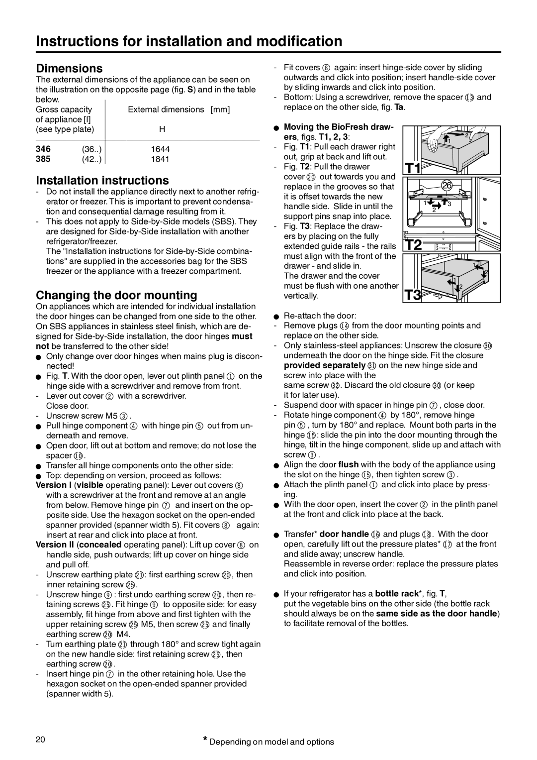
W Moving the BioFresh draw-

ers, figs. T1, 2, 3:

- Fig. T1: Pull each drawer right

out, grip at back and lift out. - Fig. T2: Pull the drawer

cover cl out towards you and replace in the grooves so that it is offset towards the new handle side. Slide in until the support pins snap into place.

- Fig. T3: Replace the draw-

ers by placing on the fully

extended guide rails - the rails must align with the front of the drawer - and slide in.

The drawer and the cover must be flush with one another vertically.

W Re-attach the door:

- Remove plugs bp from the door mounting points and replace on the other side.

- Only stainless-steel appliances: Unscrew the closure dl underneath the door on the hinge side. Fit the closure provided separately dm on the new hinge side and screw into place with the

same screw dn. Discard the old closure dl (or keep it for later use).

- Suspend door with spacer in hinge pin 7, close door. - Rotate hinge component 4 by 180°, remove hinge

pin 5, turn by 180° and replace. Mount both parts in the hinge bq: slide the pin into the door mounting through the hinge, tilt in the hinge component, slide up and attach with screw 3.

W Align the door flush with the body of the appliance using the slot on the hinge bq, then tighten screw 3.

W Attach the plinth panel 1 and click into place by press- ing.

W With the door open, insert the cover 2 in the plinth panel at the front and click into place at the back.

W Transfer* door handle br and plugs bt. With the door open, carefully lift out the pressure plates* bs at the front and slide away; unscrew handle.

Reassemble in reverse order: replace the pressure plates and click into position.

W If your refrigerator has a bottle rack*, fig. T,

put the vegetable bins on the other side (the bottle rack should always be on the same side as the door handle) to facilitate removal of the bottles.

20

* Depending on model and options

Page 10
Image 10
Liebherr 7082 212-02 manual Instructions for installation and modification, Dimensions, Installation instructions

7082 212-02 specifications

The Liebherr 7082 212-02 is a highly efficient excavator that showcases the brand’s commitment to innovation and performance in the construction and earthmoving industry. This model is a standout choice for both large-scale construction projects and smaller applications due to its impressive specifications and advanced technology.

One of the primary features of the Liebherr 7082 212-02 is its powerful engine, which is designed to provide maximum productivity while minimizing fuel consumption. The machine is equipped with a robust diesel engine that complies with the latest emissions standards, ensuring that it meets environmental regulations without compromising performance. This balance of power and efficiency makes it suitable for various job sites and applications.

In terms of operational capabilities, the Liebherr 7082 212-02 boasts an impressive digging depth and reach, allowing it to handle a wide range of tasks with ease. Its hydraulic system delivers powerful lifting and digging forces, which are critical for heavy-duty applications. The hydraulic components are designed for durability and efficiency, enhancing the machine’s overall operational performance.

Another key characteristic of the 7082 212-02 is its advanced technology. Liebherr has integrated cutting-edge telematics into the excavator, providing real-time data on machine performance, location, and maintenance needs. This feature not only helps in optimizing usage and reducing downtime but also plays a crucial role in predictive maintenance, ultimately extending the lifespan of the equipment.

The comfort and safety of the operator are also prioritized in the design of the Liebherr 7082 212-02. The spacious cab is equipped with modern controls and ergonomic seating, ensuring that the operator can work efficiently throughout the day. Enhanced visibility and intuitive controls contribute to a safer working environment, reducing the likelihood of accidents on site.

Additionally, the Liebherr 7082 212-02 is designed with versatility in mind, allowing for quick attachment changes. This adaptability enables operators to switch between various tools and attachments, enhancing the machine's functionality for different tasks, including grading, digging, and material handling.

Overall, the Liebherr 7082 212-02 is a remarkable excavator that combines power, efficiency, and advanced technology. Its robust performance, operator comfort, and adaptability make it an ideal choice for contractors looking to maximize productivity while maintaining operational efficiency. As industries continue to evolve, the Liebherr 7082 212-02 stands out as a reliable partner in construction and earthmoving projects.