7085638-01 specifications
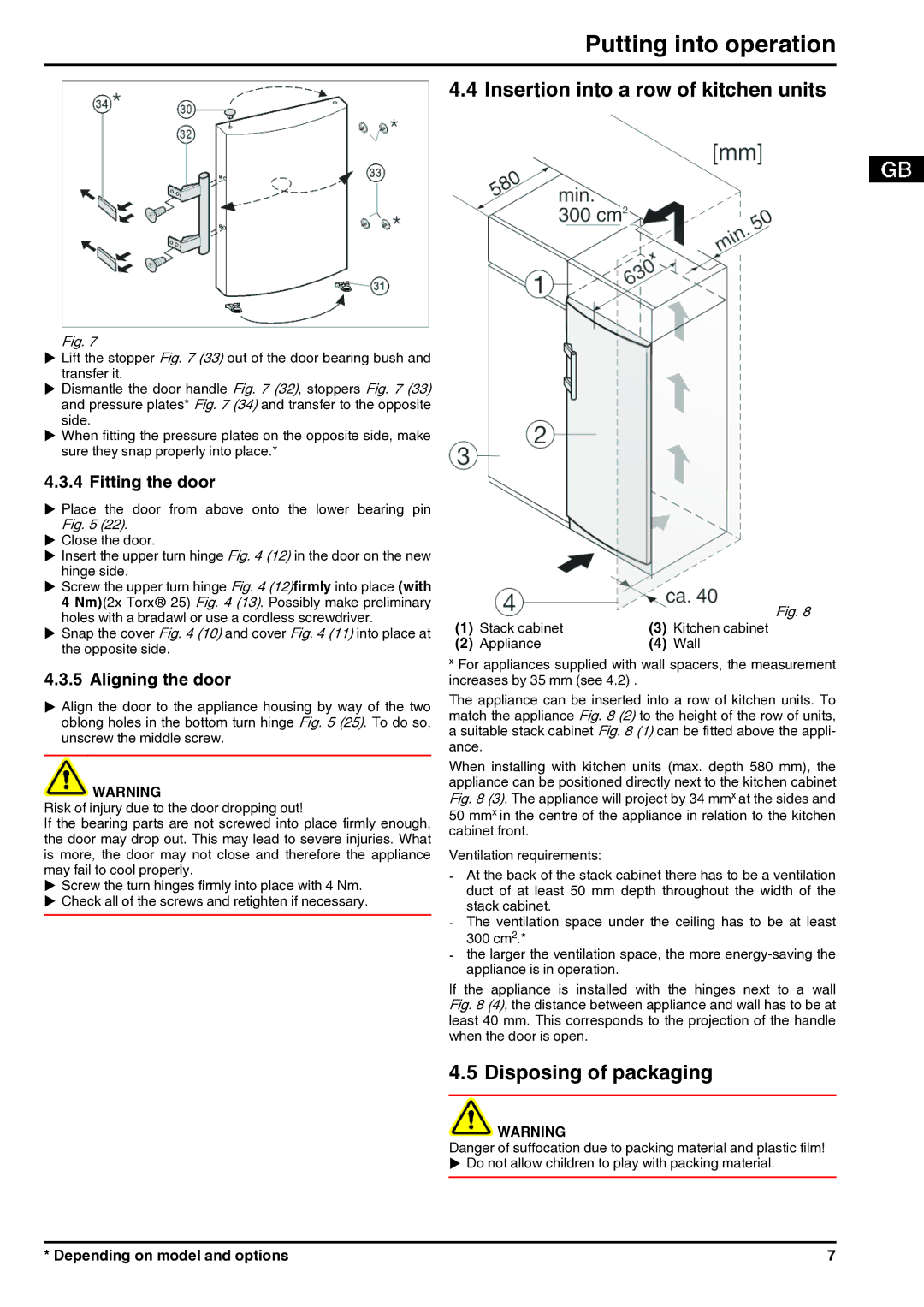
The Liebherr 7085638-01 is an advanced component that exemplifies the company’s commitment to innovation and quality in the field of industrial machinery. Liebherr, a global leader in construction equipment and mobile cranes, has engineered this component with a focus on reliability, efficiency, and performance.One of the main features of the Liebherr 7085638-01 is its robust construction. Designed to withstand the rigors of heavy-duty applications, it offers superior durability and longevity, making it an ideal choice for various construction and industrial operations. This component is crafted using high-quality materials that enhance its resistance to wear and tear, ensuring optimal performance over extended periods.
In terms of technology, the Liebherr 7085638-01 incorporates state-of-the-art engineering advancements. It employs precision manufacturing techniques that guarantee consistent quality and performance. The incorporation of advanced electronic systems allows for enhanced functionality, providing users with greater control and automation capabilities. This integration reduces operational costs and minimizes downtime, which is a critical factor in maintaining productivity on job sites.
The Liebherr 7085638-01 is known for its efficient energy consumption. It utilizes sophisticated mechanisms that optimize power usage, leading to reduced fuel consumption and lower emissions. This focus on environmental sustainability aligns with global trends toward greener construction practices, making the component a responsible choice for modern applications.
Another significant characteristic is its compatibility with a wide range of Liebherr machinery. The versatile design allows for easy integration into various models, providing users with flexibility in equipment selection. This interoperability enhances operational efficiency, as users can seamlessly transition between different machines without the need for extensive modifications.
Furthermore, the Liebherr 7085638-01 comes with comprehensive support services. Liebherr’s dedication to customer satisfaction includes providing technical assistance, maintenance guidance, and readily available spare parts. This commitment ensures that users can keep their equipment running smoothly, thus maximizing uptime and operational efficiency.
In conclusion, the Liebherr 7085638-01 is a standout component in the realm of industrial machinery, showcasing exceptional durability, cutting-edge technology, energy efficiency, versatility, and unparalleled customer support. Its design and features make it an optimal choice for construction professionals seeking reliable and high-performing equipment.

