PLANNING INFORMATION
Unit Dimensions - Figure 1 | Unit Venting - Figure 3 |
| HC 20 appliances do not require any ventilation |
| openings in the cabinet. The required airflow is |
| directed through the toe kick area. |
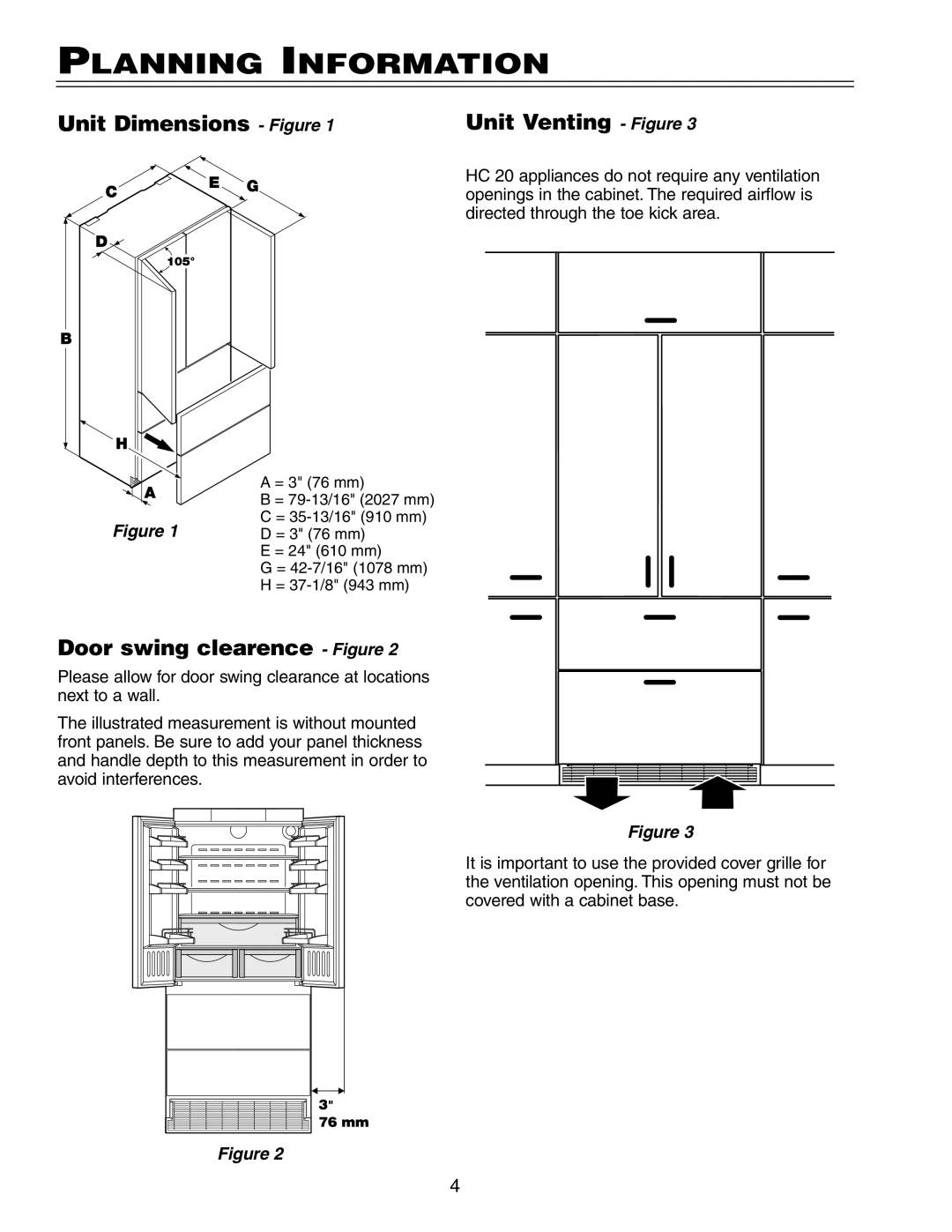
| A = 3" (76 mm) |
| B = |
Figure 1 | C = |
D = 3" (76 mm) | |
| E = 24" (610 mm) |
| G = |
| H = |
Door swing clearence - Figure 2
Please allow for door swing clearance at locations next to a wall.
The illustrated measurement is without mounted front panels. Be sure to add your panel thickness and handle depth to this measurement in order to avoid interferences.
Figure 2
Figure 3
It is important to use the provided cover grille for the ventilation opening. This opening must not be covered with a cabinet base.
4