Manuals
/
Liebherr
/
Kitchen Appliance
/
Refrigerator
Liebherr
HC 20
manual
Frameless Cabinet Figure
Models:
HC 20
1
8
18
18
Download
18 pages
62.41 Kb
5
6
7
8
9
10
11
12
Install
Safety
Page 8
Image 8
P
LANNING
I
NFORMATION
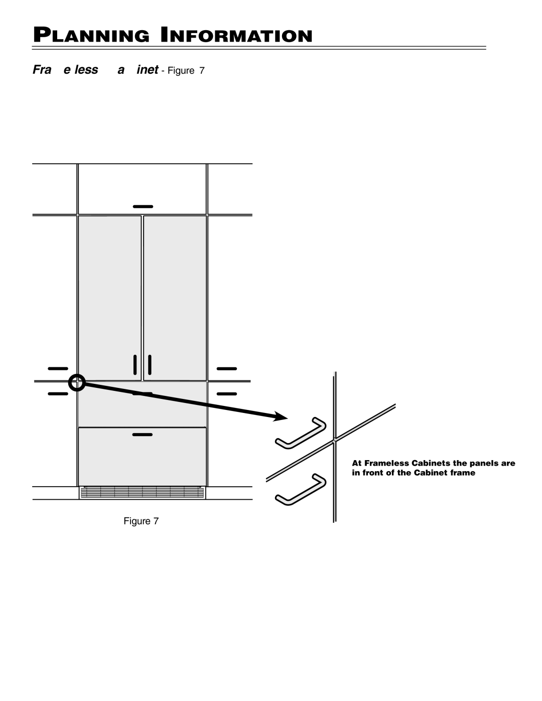
Frameless Cabinet
- Figure 7
At Frameless Cabinets the panels are in front of the Cabinet frame.
Figure 7
8
Page 7
Page 9
Page 8
Image 8
Page 7
Page 9
Contents
Instructions de montage
For Fully Integrated NoFrost Combined Refrigerator-Freezers
Please Read and Follow These Instructions
Installation Guidelines
Door swing clearence Figure
Unit Dimensions Figure Unit Venting Figure
Planning Information
Cabinet Opening Dimensions Figure
= 36 914 mm
Framed Cabinet Figure
Panel Dimensions Framed Cabinet Design Figure
Frameless Cabinet Figure
Panel Dimensions Frameless Cabinet Design Figure
Blocking for Safety
Mounting the anti tipping device on concrete floors
Mounting the anti tipping device on wooden floors
Mounting the anti tipping device in cabinets deeper than
Safety Instructions and Warnings
Icemaker
IceMaker
Water Connection
Connection to the Water Supply
Installation
Leveling the appliance Figure
Fasten the appliance in the recess
Before mounting the door panels
Mounting the attachment brackets onto the door panels Figure
Mounting the freezer drawer
Mounting the refrigerator door
Screws Figure
Mounting the ventilation grille
Top
Page
Image
Contents