3
21
16
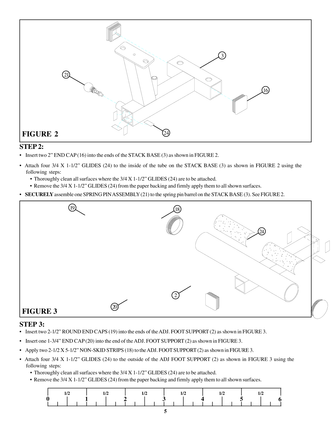
STEP 2:
•Insert two 2” END CAP (16) into the ends of the STACK BASE (3) as shown in FIGURE 2.
•Attach four 3/4 X 1-1/2” GLIDES (24) to the inside of the tube on the STACK BASE (3) as shown in FIGURE 2 using the following steps:
•Thoroughly clean all surfaces where the 3/4 X 1-1/2” GLIDES (24) are to be attached.
•Remove the 3/4 X 1-1/2” GLIDES (24) from the paper backing and firmly apply them to all shown surfaces.
•SECURELY assemble one SPRING PIN ASSEMBLY (21) to the spring pin barrel on the STACK BASE (3). See FIGURE 2.
•Insert two 2-1/2” ROUND END CAPS (19) into the ends of the ADJ. FOOT SUPPORT (2) as shown in FIGURE 3.
•Insert one 1-3/4” END CAP (20) into the end of the ADJ. FOOT SUPPORT (2) as shown in FIGURE 3.
•Apply two 2-1/2 X 5-1/2” NON-SKID STRIPS (18) to the ADJ. FOOT SUPPORT (2) as shown in FIGURE 3.
•Attach four 3/4 X 1-1/2” GLIDES (24) to the outside of the ADJ FOOT SUPPORT (2) as shown in FIGURE 3 using the following steps:
•Thoroughly clean all surfaces where the 3/4 X 1-1/2” GLIDES (24) are to be attached.
•Remove the 3/4 X 1-1/2” GLIDES (24) from the paper backing and firmly apply them to all shown surfaces.
| 1/2 | | 1/2 | | 1/2 | | 1/2 | | 1/2 | | | 1/2 | |
0 | | | 1 | | | 2 | | | 3 | | | 4 | | | 5 | | 6 |
| | | | | | | | | | | | | | | | | | | | | | | | |