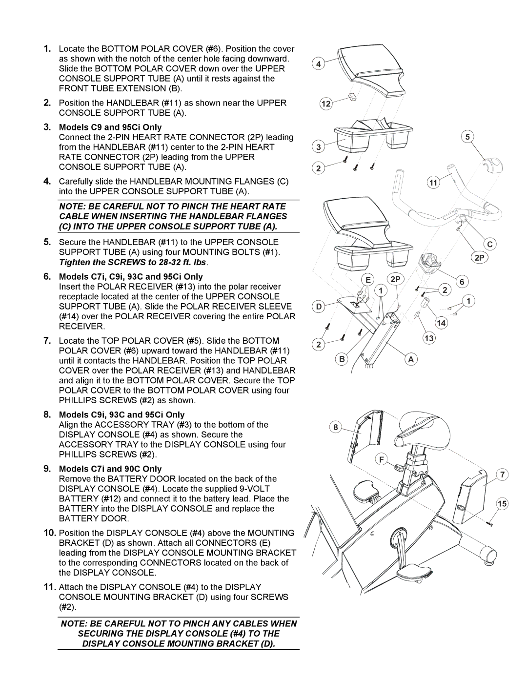
1.Locate the BOTTOM POLAR COVER (#6). Position the cover as shown with the notch of the center hole facing downward. Slide the BOTTOM POLAR COVER down over the UPPER CONSOLE SUPPORT TUBE (A) until it rests against the
FRONT TUBE EXTENSION (B).
2.Position the HANDLEBAR (#11) as shown near the UPPER CONSOLE SUPPORT TUBE (A).
3.Models C9 and 95Ci Only
Connect the
4.Carefully slide the HANDLEBAR MOUNTING FLANGES (C) into the UPPER CONSOLE SUPPORT TUBE (A).
NOTE: BE CAREFUL NOT TO PINCH THE HEART RATE CABLE WHEN INSERTING THE HANDLEBAR FLANGES
(C) INTO THE UPPER CONSOLE SUPPORT TUBE (A).
5.Secure the HANDLEBAR (#11) to the UPPER CONSOLE SUPPORT TUBE (A) using four MOUNTING BOLTS (#1). Tighten the SCREWS to
6.Models C7i, C9i, 93C and 95Ci Only
Insert the POLAR RECEIVER (#13) into the polar receiver receptacle located at the center of the UPPER CONSOLE SUPPORT TUBE (A). Slide the POLAR RECEIVER SLEEVE (#14) over the POLAR RECEIVER covering the entire POLAR RECEIVER.
7.Locate the TOP POLAR COVER (#5). Slide the BOTTOM POLAR COVER (#6) upward toward the HANDLEBAR (#11) until it contacts the HANDLEBAR. Position the TOP POLAR COVER over the POLAR RECEIVER (#13) and HANDLEBAR and align it to the BOTTOM POLAR COVER. Secure the TOP POLAR COVER to the BOTTOM POLAR COVER using four PHILLIPS SCREWS (#2) as shown.
8.Models C9i, 93C and 95Ci Only
Align the ACCESSORY TRAY (#3) to the bottom of the DISPLAY CONSOLE (#4) as shown. Secure the ACCESSORY TRAY to the DISPLAY CONSOLE using four PHILLIPS SCREWS (#2).
9.Models C7i and 90C Only
Remove the BATTERY DOOR located on the back of the DISPLAY CONSOLE (#4). Locate the supplied
BATTERY DOOR.
10.Position the DISPLAY CONSOLE (#4) above the MOUNTING BRACKET (D) as shown. Attach all CONNECTORS (E) leading from the DISPLAY CONSOLE MOUNTING BRACKET to the corresponding CONNECTORS located on the back of the DISPLAY CONSOLE.
11.Attach the DISPLAY CONSOLE (#4) to the DISPLAY CONSOLE MOUNTING BRACKET (D) using four SCREWS (#2).
4
12
![]()
![]()
![]()
![]()
![]() 5 3
5 3 ![]()
![]()
![]()
![]()
![]()
![]()
![]()
![]()
![]()
2
11
C
2P
E | 2P | 6 |
| 1 | 2 |
D |
| 1 |
|
| |
|
| 14 |
2 |
| 13 |
|
| |
B |
| A |
8
F
7
15
NOTE: BE CAREFUL NOT TO PINCH ANY CABLES WHEN
SECURING THE DISPLAY CONSOLE (#4) TO THE DISPLAY CONSOLE MOUNTING BRACKET (D).