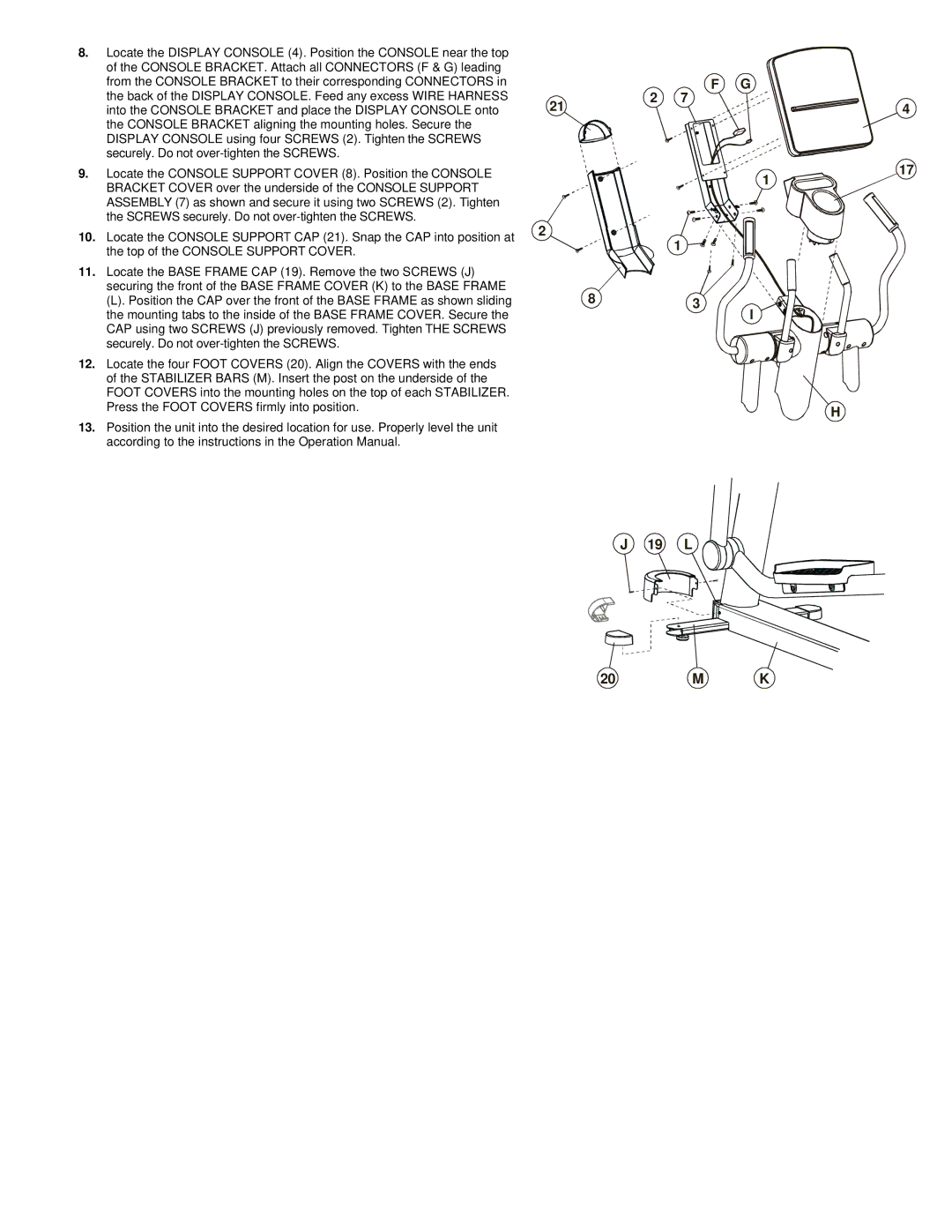
8. | Locate the DISPLAY CONSOLE (4). Position the CONSOLE near the top |
| of the CONSOLE BRACKET. Attach all CONNECTORS (F & G) leading |
| from the CONSOLE BRACKET to their corresponding CONNECTORS in |
| the back of the DISPLAY CONSOLE. Feed any excess WIRE HARNESS |
| into the CONSOLE BRACKET and place the DISPLAY CONSOLE onto |
| the CONSOLE BRACKET aligning the mounting holes. Secure the |
| DISPLAY CONSOLE using four SCREWS (2). Tighten the SCREWS |
| securely. Do not |
9. | Locate the CONSOLE SUPPORT COVER (8). Position the CONSOLE |
| BRACKET COVER over the underside of the CONSOLE SUPPORT |
| ASSEMBLY (7) as shown and secure it using two SCREWS (2). Tighten |
| the SCREWS securely. Do not |
| 2 | 7 | F G |
|
21 |
| 4 | ||
|
|
| ||
|
|
| 1 | 17 |
|
|
|
|
10. | Locate the CONSOLE SUPPORT CAP (21). Snap the CAP into position at |
| the top of the CONSOLE SUPPORT COVER. |
11. | Locate the BASE FRAME CAP (19). Remove the two SCREWS (J) |
| securing the front of the BASE FRAME COVER (K) to the BASE FRAME |
| (L). Position the CAP over the front of the BASE FRAME as shown sliding |
| the mounting tabs to the inside of the BASE FRAME COVER. Secure the |
| CAP using two SCREWS (J) previously removed. Tighten THE SCREWS |
| securely. Do not |
12. | Locate the four FOOT COVERS (20). Align the COVERS with the ends |
| of the STABILIZER BARS (M). Insert the post on the underside of the |
| FOOT COVERS into the mounting holes on the top of each STABILIZER. |
| Press the FOOT COVERS firmly into position. |
13. | Position the unit into the desired location for use. Properly level the unit |
| according to the instructions in the Operation Manual. |
2
1
83
J 19 L
I
H
