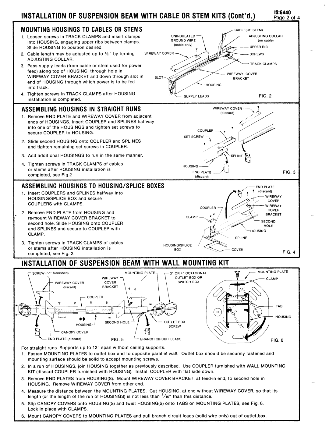
IS:6440 specifications
Lightolier IS:6440 is a high-performance lighting fixture that has gained popularity among designers, architects, and homeowners due to its innovative features and sleek design. This sophisticated lighting solution is ideal for both residential and commercial applications, providing versatility in various settings.One of the primary features of the IS:6440 is its advanced LED technology. This fixture is designed to deliver exceptional lumens per watt, ensuring energy efficiency without compromising on brightness. The LED setup not only reduces energy consumption but also has a significantly longer lifespan compared to traditional lighting options, resulting in lower maintenance costs and less frequent replacements.
The IS:6440 is equipped with a unique optical system that provides uniform light distribution. This system minimizes glare while maximizing the effective illumination of the space. Whether used in a living room, office, or gallery, the light emitted by the IS:6440 creates an inviting atmosphere, highlighting architectural details and enhancing decorative elements.
Another notable characteristic of the Lightolier IS:6440 is its adaptability. It includes various mounting options, enabling it to seamlessly integrate into different design schemes and environments. The fixture can be surface-mounted, recessed, or suspended, making it a versatile choice for diverse applications. This adaptability also extends to dimming capabilities, allowing users to create the desired ambiance by adjusting light levels as needed.
The design of the IS:6440 is both modern and minimalist, featuring clean lines that suit contemporary interiors. Available in a range of finishes, the fixture can complement any color scheme or design aesthetic, adding a touch of elegance to the space. Furthermore, its slim profile ensures that it does not overwhelm the existing decor, making it a subtle yet impactful addition.
In conclusion, the Lightolier IS:6440 is an exceptional lighting fixture that combines cutting-edge technology with aesthetic appeal. Its energy-efficient LED technology, superior optical system, adaptability in installation, and modern design make it a prime choice for anyone looking to enhance their lighting experience. Whether you're illuminating a residential space or a commercial setting, the IS:6440 delivers quality and versatility that meet the needs of diverse applications.

