SEQUENCE OF OPERATION
IMPINGER ADVANTAGE
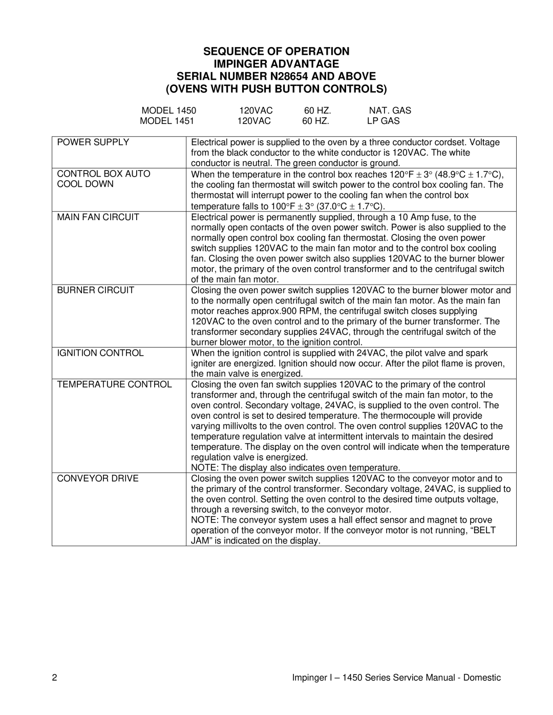
SERIAL NUMBER N28654 AND ABOVE (OVENS WITH PUSH BUTTON CONTROLS)
MODEL 1450 | 120VAC | 60 HZ. | NAT. GAS |
MODEL 1451 | 120VAC | 60 HZ. | LP GAS |
POWER SUPPLY
CONTROL BOX AUTO COOL DOWN
MAIN FAN CIRCUIT
BURNER CIRCUIT
IGNITION CONTROL
TEMPERATURE CONTROL
CONVEYOR DRIVE
Electrical power is supplied to the oven by a three conductor cordset. Voltage from the black conductor to the white conductor is 120VAC. The white conductor is neutral. The green conductor is ground.
When the temperature in the control box reaches 120°F ± 3° (48.9°C ± 1.7°C), the cooling fan thermostat will switch power to the control box cooling fan. The thermostat will interrupt power to the cooling fan when the control box temperature falls to 100°F ± 3° (37.0°C ± 1.7°C).
Electrical power is permanently supplied, through a 10 Amp fuse, to the normally open contacts of the oven power switch. Power is also supplied to the normally open control box cooling fan thermostat. Closing the oven power switch supplies 120VAC to the main fan motor and to the control box cooling fan. Closing the oven power switch also supplies 120VAC to the burner blower motor, the primary of the oven control transformer and to the centrifugal switch of the main fan motor.
Closing the oven power switch supplies 120VAC to the burner blower motor and to the normally open centrifugal switch of the main fan motor. As the main fan motor reaches approx.900 RPM, the centrifugal switch closes supplying 120VAC to the oven control and to the primary of the burner transformer. The transformer secondary supplies 24VAC, through the centrifugal switch of the burner blower motor, to the ignition control.
When the ignition control is supplied with 24VAC, the pilot valve and spark igniter are energized. Ignition should now occur. After the pilot flame is proven, the main valve is energized.
Closing the oven fan switch supplies 120VAC to the primary of the control transformer and, through the centrifugal switch of the main fan motor, to the oven control. Secondary voltage, 24VAC, is supplied to the oven control. The oven control is set to desired temperature. The thermocouple will provide varying millivolts to the oven control. The oven control supplies 120VAC to the temperature regulation valve at intermittent intervals to maintain the desired temperature. The display on the oven control will indicate when the temperature regulation valve is energized.
NOTE: The display also indicates oven temperature.
Closing the oven power switch supplies 120VAC to the conveyor motor and to the primary of the control transformer. Secondary voltage, 24VAC, is supplied to the oven control. Setting the oven control to the desired time outputs voltage, through a reversing switch, to the conveyor motor.
NOTE: The conveyor system uses a hall effect sensor and magnet to prove operation of the conveyor motor. If the conveyor motor is not running, “BELT JAM” is indicated on the display.
2 | Impinger I – 1450 Series Service Manual - Domestic |