OPERATION | ||
|
|
|
WELDER OPERATION
![]() WARNING
WARNING
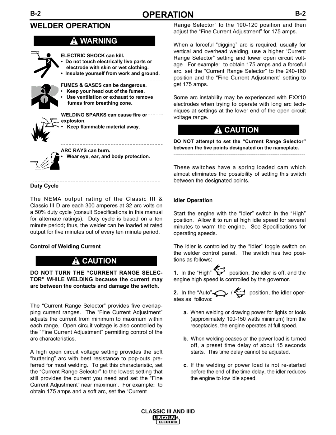
ELECTRIC SHOCK can kill.
•Do not touch electrically live parts or electrode with skin or wet clothing.
•Insulate yourself from work and ground.
FUMES & GASES can be dangerous.
• Keep your head out of the fumes.
•Use ventilation or exhaust to remove fumes from breathing zone.
WELDING SPARKS can cause fire or ![]()
![]() explosion.
explosion.
![]()
![]() • Keep flammable material away.
• Keep flammable material away.
ARC RAYS can burn.
• Wear eye, ear, and body protection.
Duty Cycle
The NEMA output rating of the Classic III & Classic III D are each 300 amperes at 32 arc volts on a 50% duty cycle (consult Specifications in this manual for alternate ratings). Duty cycle is based on a ten minute period; thus, the welder can be loaded at rated output for five minutes out of every ten minute period.
Control of Welding Current
![]() CAUTION
CAUTION
DO NOT TURN THE “CURRENT RANGE SELEC- TOR” WHILE WELDING because the current may arc between the contacts and damage the switch.
The “Current Range Selector” provides five overlap- ping current ranges. The “Fine Current Adjustment” adjusts the current from minimum to maximum within each range. Open circuit voltage is also controlled by the “Fine Current Adjustment” permitting control of the arc characteristics.
A high open circuit voltage setting provides the soft “buttering” arc with best resistance to
Range Selector” to the
When a forceful “digging” arc is required, usually for vertical and overhead welding, use a higher “Current Range Selector” setting and lower open circuit volt- age. For example: to obtain 175 amps and a forceful arc, set the “Current Range Selector” to the
Some arc instability may be experienced with EXX10 electrodes when trying to operate with long arc tech- niques at settings at the lower end of the open circuit voltage range.
![]() CAUTION
CAUTION
DO NOT attempt to set the “Current Range Selector” between the five points designated on the nameplate.
These switches have a spring loaded cam which almost eliminates the possibility of setting this switch between the designated points.
Idler Operation
Start the engine with the “Idler” switch in the “High” position. Allow it to run at high idle speed for several minutes to warm the engine. See Specifications for operating speeds.
The idler is controlled by the “Idler” toggle switch on the welder control panel. The switch has two posi- tions as follows:
1.In the “High” ![]() position, the idler is off, and the engine high speed is controlled by the governor.
position, the idler is off, and the engine high speed is controlled by the governor.
2.In the “Auto”![]() /
/ ![]()
![]() position, the idler oper- ates as follows:
position, the idler oper- ates as follows:
a.When welding or drawing power for lights or tools (approximately
b.When welding ceases or the power load is turned off, a preset time delay of about 15 seconds starts. This time delay cannot be adjusted.
c.If the welding or power load is not
CLASSIC III AND IIID