|
| INSTALLATION |
| |||||
|
|
|
|
|
|
|
|
|
| b. Remove the molded gas plug fitting on the side of the |
|
|
| ||||
| feeder end handle and replace it with the barbed brass fit- |
|
|
|
| |||
| ting provided in the kit. The included wrench will fit both |
|
|
|
| |||
| the gas plug and barbed fitting. |
|
|
|
|
|
| |
| c. Attach the phone plug connector of the gun control cable |
|
|
|
| |||
| provided to the trigger connector on the front of the |
|
|
|
| |||
| Hobart feeder. |
|
|
|
|
|
| |
|
|
|
|
| ||||
|
|
|
|
|
| |||
| d. Place one tubing clamp onto each end of the flexible tub- | Hobart Series 2000 Feeders and Lincoln 10 Series Feeders) |
| |||||
| ing provided, approximately 2” (51 mm) in from each end. |
|
|
|
| |||
| Slide one end of the tubing onto the barbed connector on |
| a. Remove brass cable connector (see Figure B.1) from the |
| ||||
| the feeder end cable handle (step b) and move the clamp |
| connector kit and screw it onto the feeder end of the gun |
| ||||
| down near the end of the tube to assure a good gas seal. |
| cable. Tighten the connection with the wrench provided. |
| ||||
|
|
|
|
|
| b. Check that the molded gas plug fitting is sealing the gas |
| |
|
|
|
|
|
|
| ||
|
|
|
|
|
| fitting hole in the side of the feeder end handle. |
|
|
|
|
|
|
|
| c. Attach the gun control cable provided to the trigger con- |
| |
|
|
|
|
|
| nector on the front of the wire feeder. |
|
|
|
|
|
|
|
|
|
| |
|
|
|
|
|
|
| ||
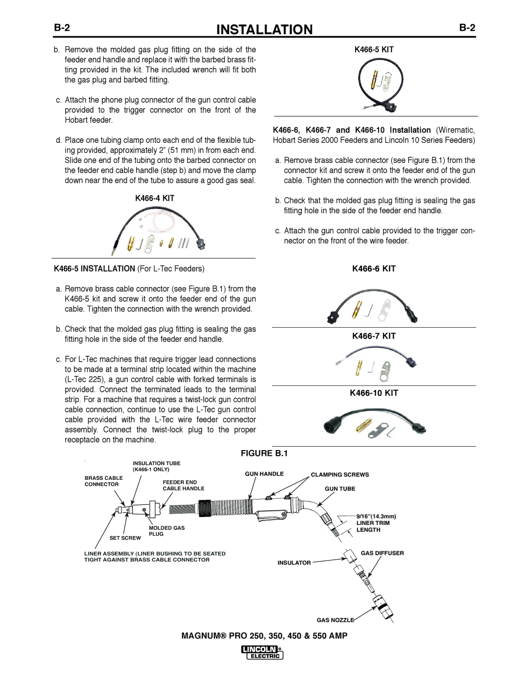
| a. Remove brass cable connector (see Figure B.1) from the |
|
|
|
| |||
|
|
|
|
| ||||
| cable. Tighten the connection with the wrench provided. |
|
|
|
| |||
b. Check that the molded gas plug fitting is sealing the gas
fitting hole in the side of the feeder end handle. |
| ||
| |||
c. For |
| ||
to be made at a terminal strip located within the machine |
| ||
| |||
|
| ||
provided. Connect the terminated leads to the terminal |
|
| |
strip. For a machine that requires a | |||
| |||
cable connection, continue to use the |
| ||
cable provided with the |
| ||
assembly. Connect the |
| ||
receptacle on the machine. |
| ||
|
|
| |
FIGURE B.1 |
| ||
INSULATION TUBE
BRASS CABLE
CONNECTORFEEDER END CABLE HANDLE
| MOLDED GAS |
SET SCREW | PLUG |
|
LINER ASSEMBLY (LINER BUSHING TO BE SEATED TIGHT AGAINST BRASS CABLE CONNECTOR
GUN HANDLE | CLAMPING SCREWS |
| GUN TUBE |
| 9/16”(14.3mm) |
| LINER TRIM |
| LENGTH |
| GAS DIFFUSER |
INSULATOR |
|
GAS NOZZLE![]()
MAGNUM® PRO 250, 350, 450 & 550 AMP
