MAINTENANCE |
|
| |||||
|
|
|
| FIGURE D.1 |
|
|
|
| TRIM CORE TUBE FLUSH WITHIN ± .125 (3.18mm) |
|
|
| 3.50 (88.9mm) | LEAD LENGTH | |
| OF CABLE JACKET. CORE TUBE MAY RETRACT | 3.25 (82.6mm) | |||||
| .30 (7.6mm) MAXIMUM AFTER TRIMMING. | (4 PLACES) |
|
| |||
|
|
|
| ||||
1.000 (25.4mm) |
| SKIN WHITE AND RED LEADS ONLY |
.875 (22.2mm) |
| TO DIMENSION SHOWN, DO NOT SKIN |
COPPER |
| THE BLUE OR THE BLACK LEAD. |
STRANDING |
| .16 (4.01mm) |
| RED | SKIN |
|
| |
|
| GUN END |
| WHITE |
|
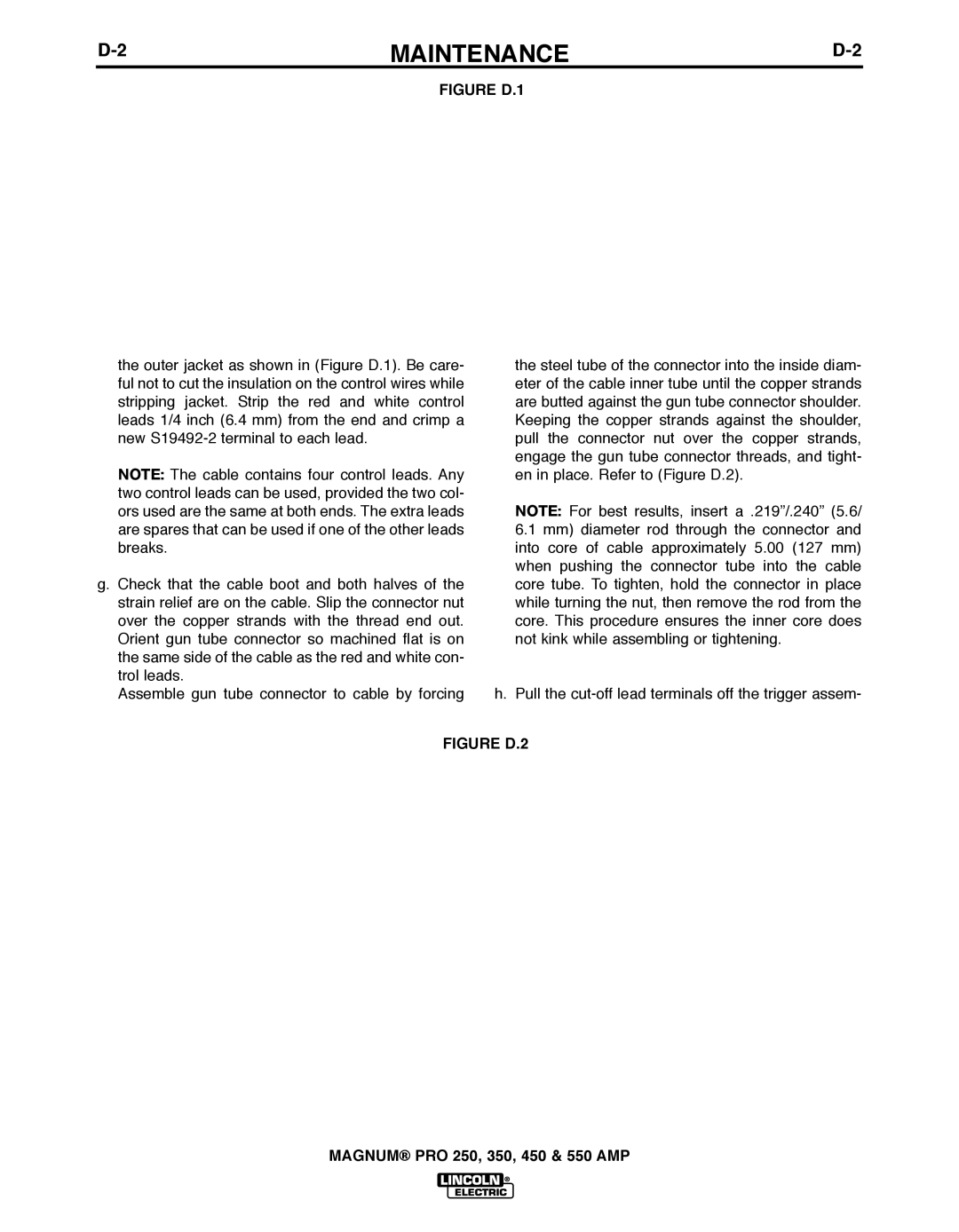
INSULATION ON THE CONTROL WIRES MUST
NOT BE CUT OR DAMAGED.
the outer jacket as shown in (Figure D.1). Be care- ful not to cut the insulation on the control wires while stripping jacket. Strip the red and white control leads 1/4 inch (6.4 mm) from the end and crimp a new
note: The cable contains four control leads. Any two control leads can be used, provided the two col- ors used are the same at both ends. The extra leads are spares that can be used if one of the other leads breaks.
g. Check that the cable boot and both halves of the strain relief are on the cable. Slip the connector nut over the copper strands with the thread end out. Orient gun tube connector so machined flat is on the same side of the cable as the red and white con- trol leads.
Assemble gun tube connector to cable by forcing
the steel tube of the connector into the inside diam- eter of the cable inner tube until the copper strands are butted against the gun tube connector shoulder. Keeping the copper strands against the shoulder, pull the connector nut over the copper strands, engage the gun tube connector threads, and tight- en in place. Refer to (Figure D.2).
note: For best results, insert a .219”/.240” (5.6/
6.1 mm) diameter rod through the connector and into core of cable approximately 5.00 (127 mm) when pushing the connector tube into the cable core tube. To tighten, hold the connector in place while turning the nut, then remove the rod from the core. This procedure ensures the inner core does not kink while assembling or tightening.
h.Pull the
FIGURE D.2
KNURLED NUT
CABLE | SPRING BOOT RETAINER | STRAIN RELIEF |
| ||
| CONNECTOR TUBE | |
|
|
STRAIN RELIEF HOUSING
SPRING BOOT
CABLE LINER
COPPER STRANDS
MALE CONE ASSEMBLY, 250A - 450A
POWER CABLE FEMALE NUT
MAGNUM® PRO 250, 350, 450 & 550 AMP