INSTALLATION | ||
|
|
|
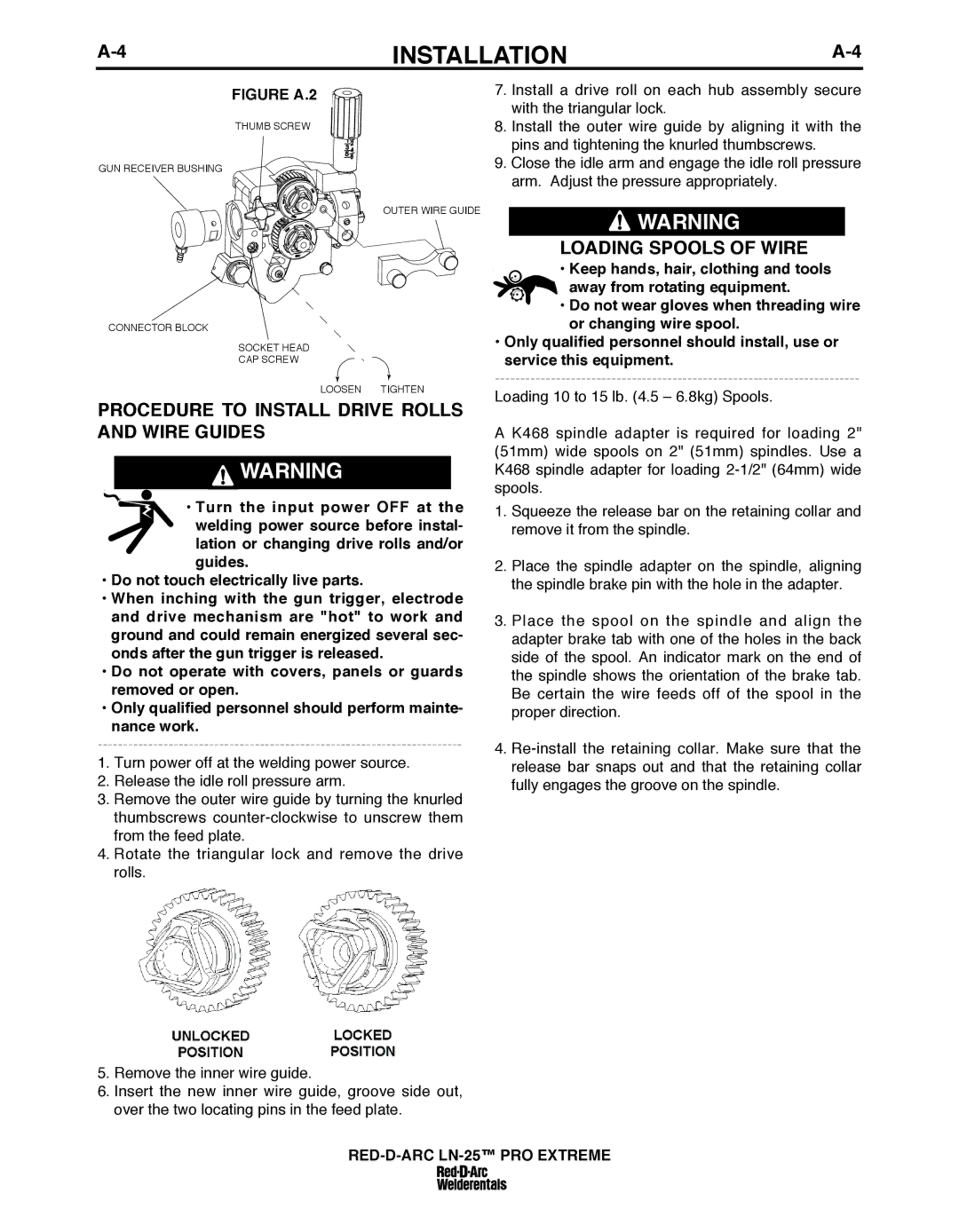
FIGuRE A.2
THUMB SCREW
GUN RECEIVER BUSHING
OUTER WIRE GUIDE
CONNECTOR BLOCK
SOCKET HEAD
CAP SCREW
LOOSEN TIGHTEN
PROCEDuRE TO INSTALL DRIVE ROLLS AND WIRE GuIDES
![]() WARNING
WARNING
•Turn the input power OFF at the welding power source before instal- lation or changing drive rolls and/or guides.
•Do not touch electrically live parts.
•When inching with the gun trigger, electrode and drive mechanism are "hot" to work and ground and could remain energized several sec- onds after the gun trigger is released.
•Do not operate with covers, panels or guards removed or open.
•Only qualified personnel should perform mainte- nance work.
1.Turn power off at the welding power source.
2.Release the idle roll pressure arm.
3.Remove the outer wire guide by turning the knurled thumbscrews
4.Rotate the triangular lock and remove the drive rolls.
5.Remove the inner wire guide.
6.Insert the new inner wire guide, groove side out, over the two locating pins in the feed plate.
7.Install a drive roll on each hub assembly secure with the triangular lock.
8.Install the outer wire guide by aligning it with the pins and tightening the knurled thumbscrews.
9.Close the idle arm and engage the idle roll pressure arm. Adjust the pressure appropriately.
![]() WARNING
WARNING
LOADING SPOOLS OF WIRE
•Keep hands, hair, clothing and tools away from rotating equipment.
•Do not wear gloves when threading wire or changing wire spool.
•Only qualified personnel should install, use or service this equipment.
Loading 10 to 15 lb. (4.5 – 6.8kg) Spools.
A K468 spindle adapter is required for loading 2" (51mm) wide spools on 2" (51mm) spindles. Use a K468 spindle adapter for loading
1.Squeeze the release bar on the retaining collar and remove it from the spindle.
2.Place the spindle adapter on the spindle, aligning the spindle brake pin with the hole in the adapter.
3.Place the spool on the spindle and align the adapter brake tab with one of the holes in the back side of the spool. An indicator mark on the end of the spindle shows the orientation of the brake tab. Be certain the wire feeds off of the spool in the proper direction.
4.