OPERATION | ||
|
|
|
(See Customer Assistance Policy in the front of this Instruction Manual)
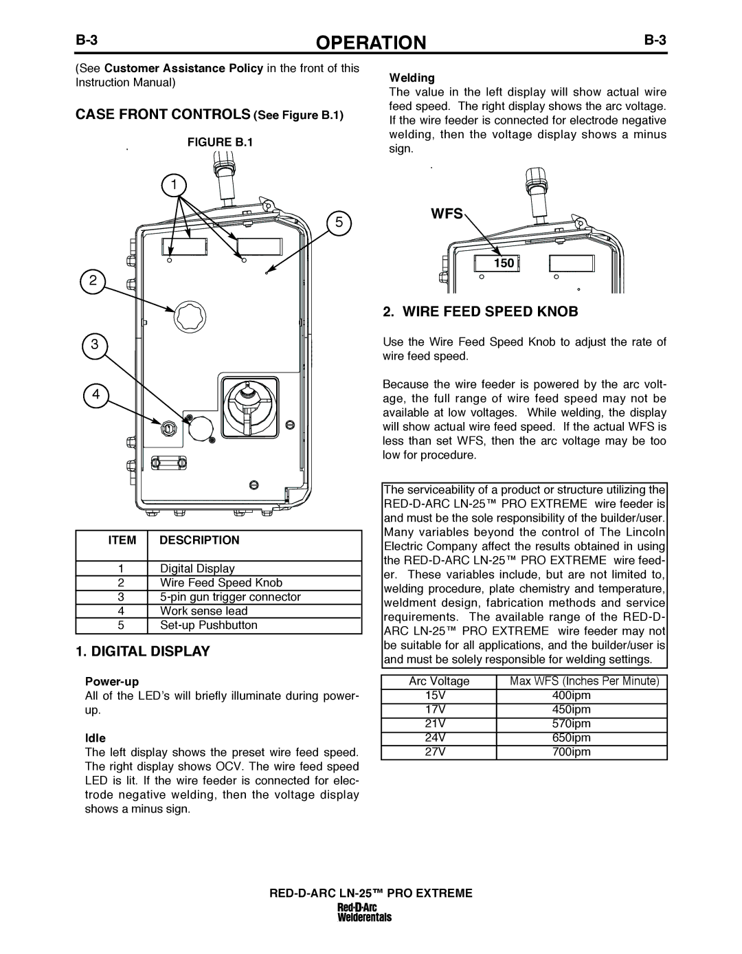
CASE FRONT CONTROLS (See Figure b.1)
FIGuRE b.1
Welding
The value in the left display will show actual wire feed speed. The right display shows the arc voltage. If the wire feeder is connected for electrode negative welding, then the voltage display shows a minus sign.
1
5
2
3
4
ITEM | DESCRIPTION |
|
|
1 | Digital Display |
2 | Wire Feed Speed Knob |
3 | |
4 | Work sense lead |
5 | |
|
|
1. DIGITAL DISPLAY
All of the LED’s will briefly illuminate during power- up.
Idle
The left display shows the preset wire feed speed. The right display shows OCV. The wire feed speed LED is lit. If the wire feeder is connected for elec- trode negative welding, then the voltage display shows a minus sign.
WFS
150 ![]()
![]()
2. WIRE FEED SPEED KNOb
Use the Wire Feed Speed Knob to adjust the rate of wire feed speed.
Because the wire feeder is powered by the arc volt- age, the full range of wire feed speed may not be available at low voltages. While welding, the display will show actual wire feed speed. If the actual WFS is less than set WFS, then the arc voltage may be too low for procedure.
The serviceability of a product or structure utilizing the
Arc Voltage | Max WFS (Inches Per Minute) |
|
|
15V | 400ipm |
|
|
17V | 450ipm |
21V | 570ipm |
24V | 650ipm |
27V | 700ipm |