Preparations
Connections
Before using the player, connect the player to a TV and/or amplifier.
Before making connections
•Do not connect the AC power cord until all other connections have been made.
•Connect VIDEO OUT of the player directly to the video input of your TV. Connecting VIDEO OUT of the player to a TV via a VCR may cause a monitor problem when playing back a
Connecting to a TV
The following sections A to C describe TV connections where only a TV is connected to the player so that you will hear sound from the TV.
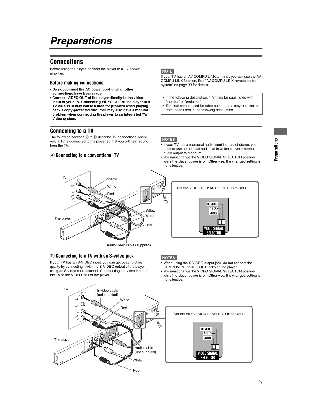
AConnecting to a conventional TV
NOTE![]()
If your TV has an AV COMPU LINK terminal, you can use the AV COMPU LINK function. See “AV COMPU LINK remote control system” on page 33 for details.
•In the following description, “TV” may be substituted with “monitor” or “projector.”
•Terminal names used for other components may be different from those used in the following description.
NOTES![]()
•If your TV has a monaural audio input instead of stereo, you need to use an optional audio cable which converts stereo audio output to monaural.
•You must change the VIDEO SIGNAL SELECTOR position while the player power is off. Otherwise, the changed setting is not effective.
Preparations
TV
IN
VIDEO | |
LE | FT |
AUDIO | |
RIG | HT |
| |
The player
Yellow
White
Red
|
|
| COM | PO | NEN | T |
|
|
|
|
| P | R | ||
|
|
|
|
|
| ||
|
|
|
| PB |
|
| |
|
|
| Y |
|
|
|
|
COAX | IAL | VIDEO |
|
|
|
|
|
|
|
| OUT |
|
| ||
|
|
| EO |
|
| ||
|
| VID |
|
| |||
|
|
|
|
| |||
LEFT |
|
|
|
|
|
|
| OPTIC | A |
|
|
|
| |
RIGHT |
| L O | UT |
|
| ITA |
| ||
DIG |
|
| ||
|
|
|
| DIO | OU | T |
AU |
| ||
|
|
REM | OTE |
|
|
|
|
| |
480p |
|
|
|
|
| ||
| 48 | 0i |
|
| AV |
| K |
|
|
|
| LIN | |||
|
|
|
| COM | PU | ||
|
|
|
|
| |||
|
| SIG | NAL |
|
|
| |
| EO |
|
|
|
| ||
VID | R |
|
|
|
| ||
| ECTO |
|
|
|
|
| |
SEL |
|
|
|
|
|
| |
Yellow
White
Red
Set the VIDEO SIGNAL SELECTOR to “480i.”
REMOTE
480p
480i |
VIDEO SIGNAL
SELECTOR
Audio/video cable (supplied)
BConnecting to a TV with an S-video jack
If your TV has an
TV |
|
|
|
|
|
|
|
|
|
|
|
|
|
|
| |||||||||
|
|
| IN |
|
|
|
|
|
|
|
|
|
|
|
| |||||||||
|
|
|
|
|
|
|
|
| (not supplied) |
|
|
|
|
|
| |||||||||
|
|
|
|
|
|
|
|
|
|
|
|
|
|
|
| |||||||||
| S |
|
|
|
|
|
|
|
|
|
|
|
|
|
| White |
|
|
|
|
|
| ||
|
| VIDEO |
|
|
|
|
|
|
|
|
|
|
|
|
|
| Red |
|
|
|
|
|
| |
|
|
|
|
|
|
|
|
|
|
|
|
|
|
|
|
|
|
|
|
|
|
|
| |
|
| LE | FT |
|
|
|
|
|
|
|
|
|
|
|
|
|
|
|
|
|
|
|
|
|
|
| AUDIO |
|
|
|
|
|
|
|
|
|
|
|
|
|
| REM | OTE |
|
|
|
|
| |
|
| RIG | HT |
|
|
|
|
|
|
|
|
|
|
|
|
|
| 48 | 0p |
|
|
|
|
|
|
|
|
|
|
|
|
|
|
|
|
|
|
|
|
| 0i |
|
|
|
|
| |||
|
|
|
|
|
|
|
|
|
|
|
|
|
|
|
|
| 48 |
|
| AV |
| K | ||
|
|
|
|
|
|
|
|
|
|
|
|
|
|
|
|
|
|
|
|
| COM | PU | LIN | |
|
|
|
|
|
|
|
|
|
|
|
|
|
|
|
|
|
|
|
|
|
| |||
|
|
|
|
|
|
|
|
|
|
|
|
|
|
|
|
|
|
|
| NAL |
|
| ||
|
|
|
|
|
|
|
|
|
|
|
|
|
|
|
|
|
|
| SIG |
|
|
| ||
|
|
|
|
|
|
|
|
|
|
|
|
|
|
|
|
|
| EO | R |
|
|
|
| |
|
|
|
|
|
|
|
|
|
|
|
|
|
|
|
|
|
| VID | ECTO |
|
|
|
|
|
|
|
|
|
|
|
|
|
|
|
|
|
|
|
|
|
|
| SEL |
|
|
|
|
|
|
|
|
|
|
|
|
|
|
|
|
|
|
|
| COM | PO | NEN | T |
|
|
|
|
|
|
|
|
|
|
|
|
|
|
|
|
|
|
|
|
|
| P | R |
|
|
|
|
|
| ||
|
|
|
|
|
|
|
|
|
|
|
|
|
|
|
|
|
|
|
|
|
|
| ||
|
|
|
|
|
|
|
|
|
|
|
|
|
|
| PB |
|
|
|
|
|
|
|
| |
|
|
|
|
|
|
|
|
|
|
|
|
|
| Y |
|
|
|
|
|
|
|
|
|
|
|
|
|
|
|
|
|
|
|
| COAX | IAL | VIDEO |
|
|
|
|
|
|
|
|
|
|
| |
|
|
|
|
|
|
|
|
|
|
|
|
|
| EO | OUT |
|
|
|
|
|
|
|
| |
The player |
|
|
|
|
|
|
|
|
|
|
| EO | VID |
|
|
|
|
|
|
|
| |||
|
|
|
|
|
|
|
|
|
|
|
|
|
|
|
|
|
|
|
|
|
| |||
|
|
|
|
|
|
|
|
|
|
|
|
|
|
|
|
|
|
|
|
|
|
|
| |
|
|
|
|
|
|
| LEFT |
|
|
|
|
|
|
|
|
|
|
|
|
|
|
|
|
|
|
|
|
|
|
|
|
|
| OPTIC | A |
|
|
|
|
|
|
|
|
|
|
|
|
|
|
|
|
|
|
|
|
|
| ITAL O |
|
|
|
|
|
|
|
| Audio cable | |||||||
|
|
|
|
|
|
| RIGHT | UT |
|
|
|
|
|
|
|
| ||||||||
|
|
|
|
|
|
|
|
|
|
|
|
|
|
|
|
|
|
|
|
|
|
|
| |
|
|
|
|
|
|
| DIG |
|
|
|
|
|
|
|
|
|
| (not supplied) | ||||||
|
|
| A | UD | IO | OU | T |
|
|
|
|
|
|
|
|
|
| |||||||
|
|
|
|
|
|
|
|
|
|
|
|
|
|
|
|
|
|
|
|
|
|
| ||
White
Red
NOTES![]()
•When using the
•You must change the VIDEO SIGNAL SELECTOR position while the player power is off. Otherwise, the changed setting is not effective.
Set the VIDEO SIGNAL SELECTOR to “480i.”
REMOTE
480p
480i |
VIDEO SIGNAL
SELECTOR
5