OPERATION | ||
|
|
|
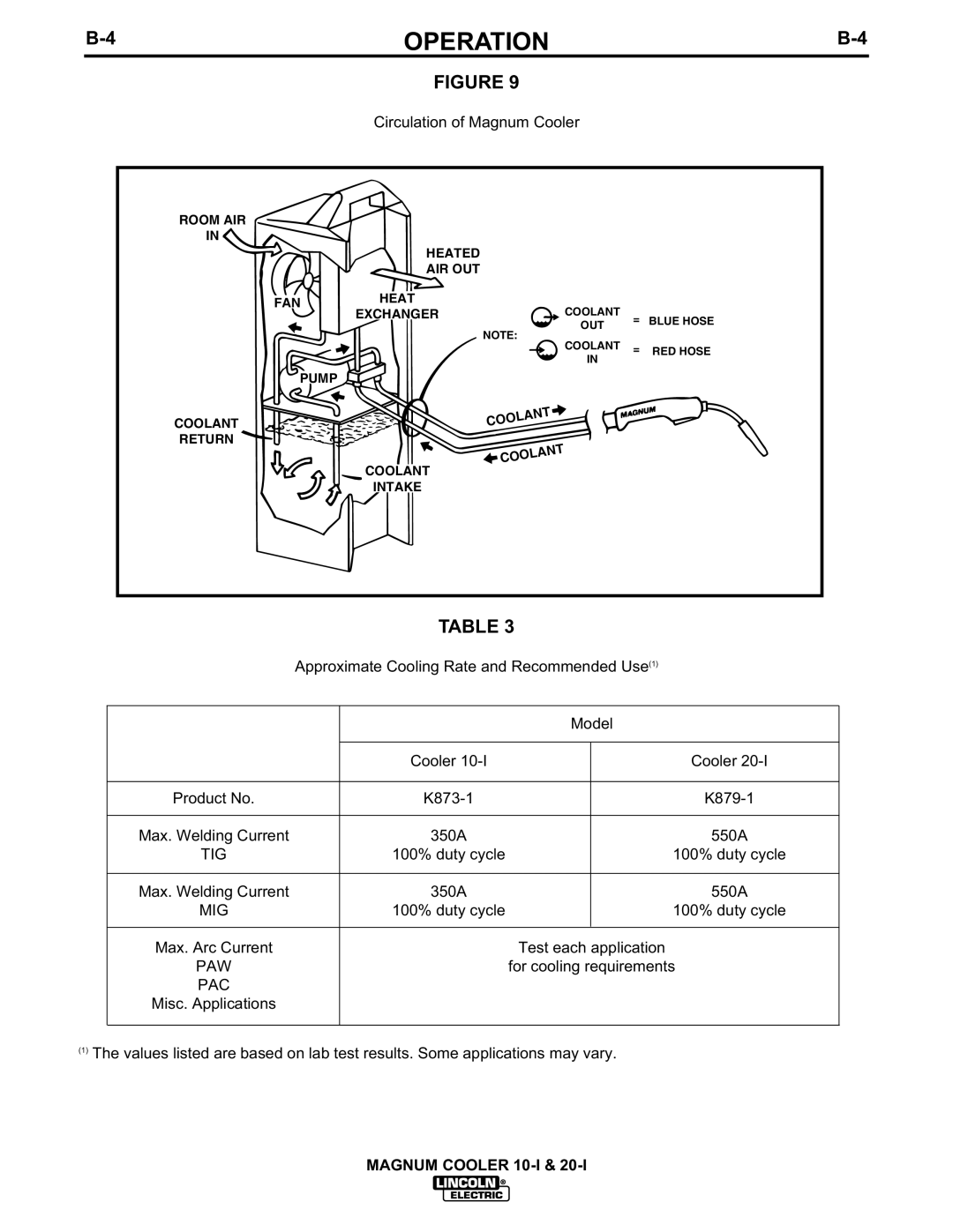
FIGURE 9
Circulation of Magnum Cooler
ROOM AIR
IN
HEATED
AIR OUT
FAN | HEAT | COOLANT |
|
|
EXCHANGER |
|
| ||
| = | BLUE HOSE | ||
|
| OUT | ||
|
|
|
| |
|
| NOTE: |
|
|
|
| COOLANT = | RED HOSE | |
|
| IN |
|
|
PUMP
COOLANT
RETURN
COOLANT
![]() COOLANT
COOLANT
COOLANT
INTAKE
TABLE 3
Approximate Cooling Rate and Recommended Use(1)
|
| Model | |
|
|
|
|
| Cooler |
| Cooler |
|
|
|
|
Product No. |
| ||
|
|
|
|
Max. Welding Current | 350A |
| 550A |
TIG | 100% duty cycle |
| 100% duty cycle |
|
|
|
|
Max. Welding Current | 350A |
| 550A |
MIG | 100% duty cycle |
| 100% duty cycle |
|
|
|
|
Max. Arc Current |
| Test each application | |
PAW |
| for cooling requirements | |
PAC |
|
|
|
Misc. Applications |
|
|
|
|
|
|
|
(1)The values listed are based on lab test results. Some applications may vary.
MAGNUM COOLER
