INSTALLATION | ||
|
|
|
INSTALLATION
![]() WARNING
WARNING
ELECTRIC SHOCK can kill.
•Disconnect input power by removing plug from receptacle before working inside Cooler.
•Use only grounded receptacle.
•Do not remove the power cord ground prong.
•Do not touch electrically “hot” parts inside Cooler.
•Have qualified personnel do the installation, main- tenance and troubleshooting work.
PRODUCT OVERVIEW
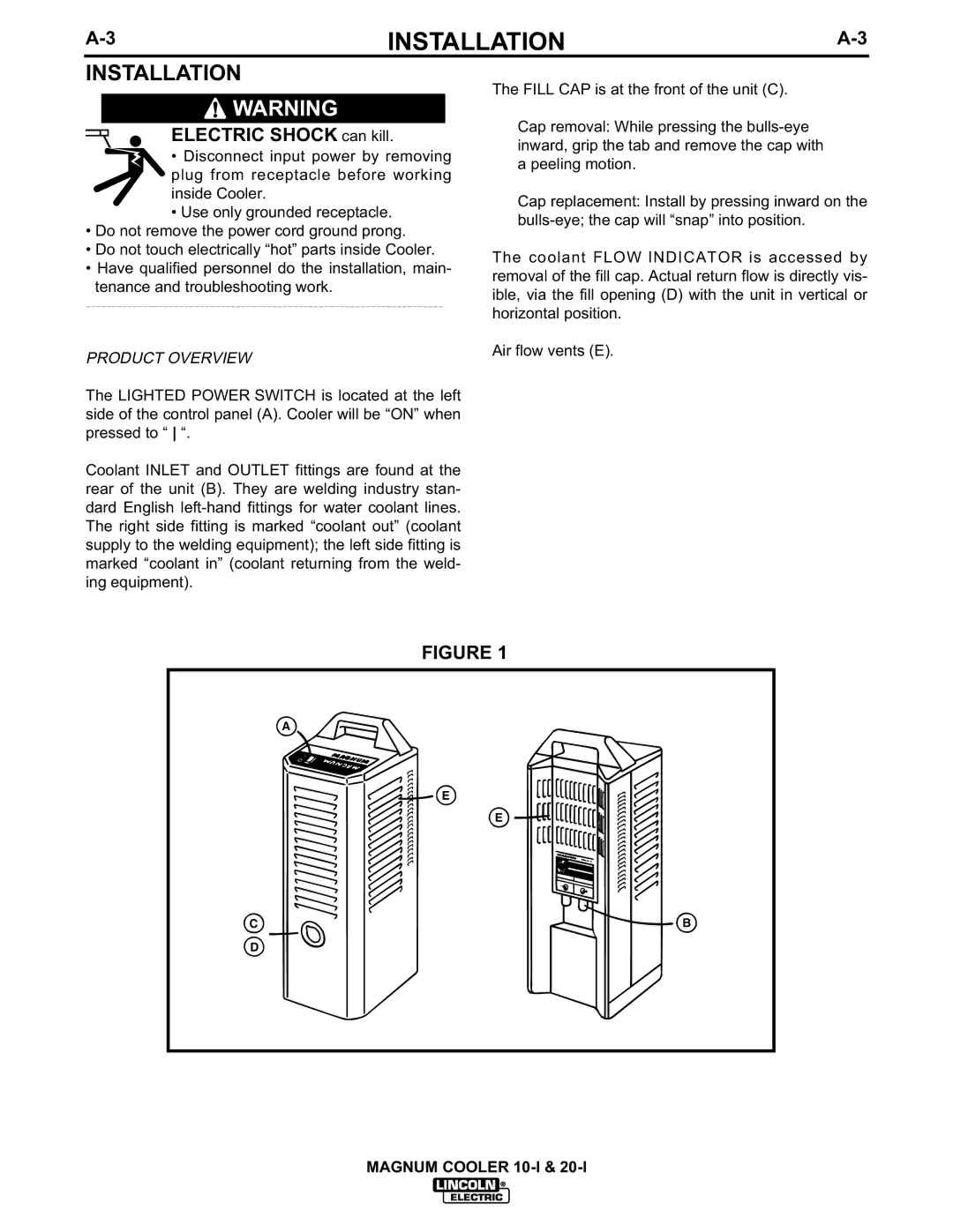
The LIGHTED POWER SWITCH is located at the left side of the control panel (A). Cooler will be “ON” when pressed to “ “.
Coolant INLET and OUTLET fittings are found at the rear of the unit (B). They are welding industry stan- dard English
The FILL CAP is at the front of the unit (C).
Cap removal: While pressing the
Cap replacement: Install by pressing inward on the
The coolant FLOW INDICATOR is accessed by removal of the fill cap. Actual return flow is directly vis- ible, via the fill opening (D) with the unit in vertical or horizontal position.
Air flow vents (E).
FIGURE 1
A
E
E
CB
D
MAGNUM COOLER