![]() CAUTION
CAUTION
Failure to follow these instructions can cause immedi- ate failure of components within the machine.
When powering welder from a generator be sure to turn off the welder first, before generator is shut down in order to prevent damage to welder.
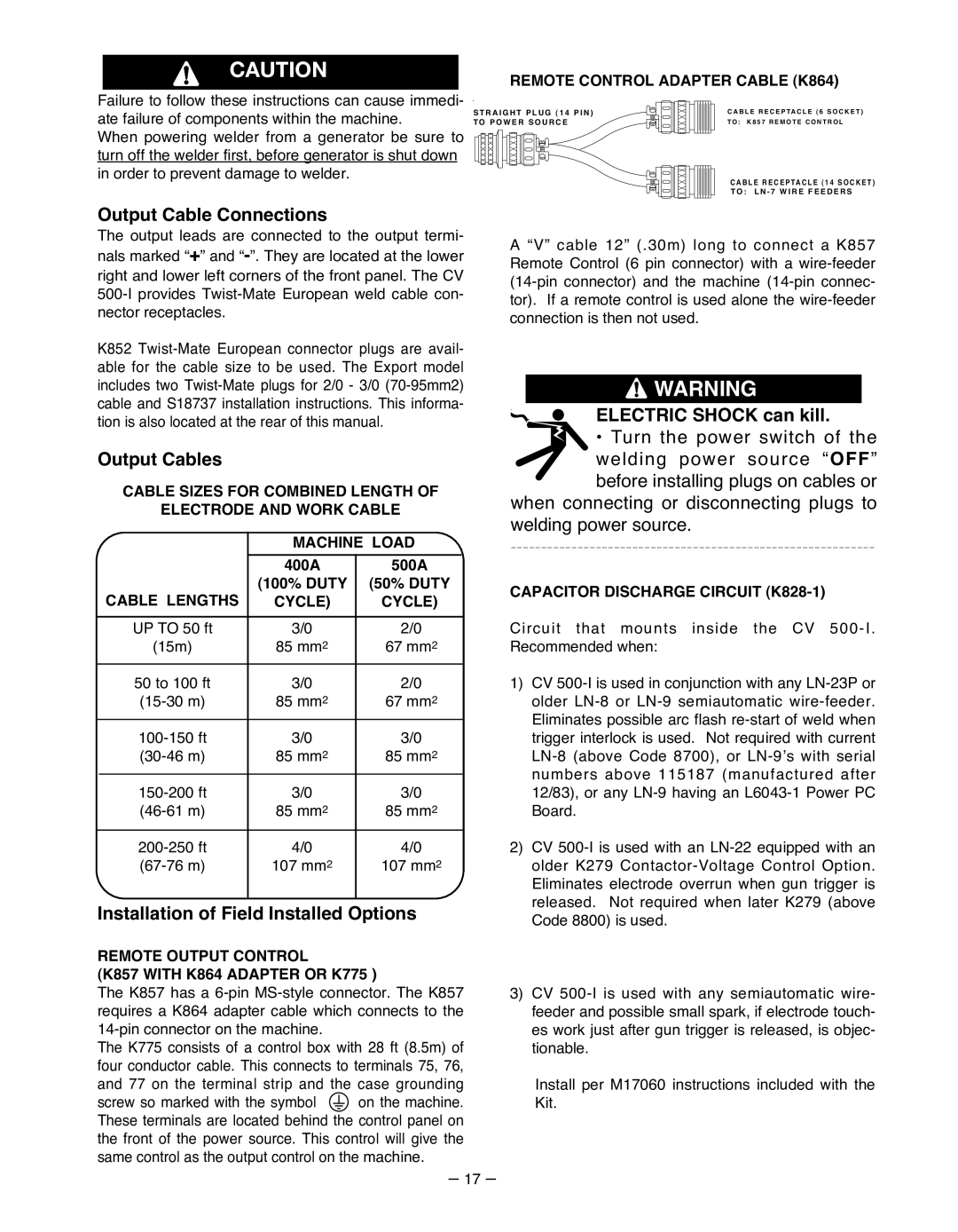
REMOTE CONTROL ADAPTER CABLE (K864)
S T R A I G H T P L U G ( 1 4 P I N ) |
|
|
|
|
|
|
|
| C A B L E R E C E P TA C L E ( 6 S O C K E T ) | |||||||
TO P O W E R S O U R C E |
|
|
|
|
|
|
|
| T O : K 8 5 7 R E M O T E C O N T R O L | |||||||
|
|
|
|
|
|
|
|
|
|
|
|
|
|
|
|
|
|
|
|
|
|
|
|
|
|
|
|
|
|
|
|
|
|
|
|
|
|
|
|
|
|
|
|
|
|
|
|
|
|
|
CABLE RECEPTACLE (14 SOCKET)
TO : L N - 7 W I R E F E E D E R S
Output Cable Connections
The output leads are connected to the output termi- nals marked “+” and
K852
Output Cables
CABLE SIzES FOR COMBINED LENGTH OF
ELECTRODE AND WORK CABLE
|
|
| MACHINE LOAD | ||
|
|
|
|
|
|
|
|
| 400A | 500A | |
|
|
| (100% DUTY | (50% DUTY | |
| CABLE LENGTHS |
| CYCLE) | CYCLE) | |
|
|
|
|
|
|
|
|
|
|
|
|
| UP TO 50 ft |
| 3/0 | 2/0 |
|
| (15m) |
| 85 mm2 | 67 mm2 | |
|
|
|
|
|
|
| 50 to 100 ft |
| 3/0 | 2/0 |
|
|
| 85 mm2 | 67 mm2 | ||
|
|
|
|
|
|
|
| 3/0 | 3/0 |
| |
|
| 85 mm2 | 85 mm2 | ||
|
|
|
|
|
|
|
| 3/0 | 3/0 |
| |
|
| 85 mm2 | 85 mm2 | ||
|
|
|
|
|
|
|
| 4/0 | 4/0 |
| |
|
| 107 mm2 | 107 mm2 | ||
|
|
|
|
|
|
Installation of Field Installed Options
REMOTE OUTPUT CONTROL
(K857 WITH K864 ADAPTER OR K775 )
The K857 has a
The K775 consists of a control box with 28 ft (8.5m) of four conductor cable. This connects to terminals 75, 76, and 77 on the terminal strip and the case grounding
screw so marked with the symbol on the machine. These terminals are located behind the control panel on the front of the power source. This control will give the same control as the output control on the machine.
– 17 –
A “V” cable 12” (.30m) long to connect a K857 Remote Control (6 pin connector) with a
![]() WARNING
WARNING
ELECTRIC SHOCK can kill.
•Turn the power switch of the welding power source “OFF” before installing plugs on cables or
when connecting or disconnecting plugs to welding power source.
CAPACITOR DISCHARGE CIRCUIT (K828-1)
Circuit that mounts inside the CV
1)CV
2)CV
3)CV
Install per M17060 instructions included with the Kit.