Manuals
/
Lincoln Electric
/
Power Tools
/
Welder
Lincoln Electric
IM490-C
manual
Diagrams, Dimension Print
Models:
IM490-C
1
32
37
37
Download
37 pages
16.47 Kb
29
30
31
32
33
34
35
36
Troubleshooting
Install
Wiring DIAGRAM- Codes 10102
Input Fuse and Supply Wire
Dimension
Maintenance
Symptoms
Accessories
Controls and Settings
Remote Control Receptacle
Page 32
Image 32
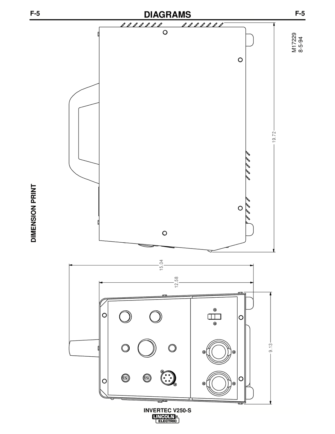
F-5
DIAGRAMS
F-5
DIMENSION PRINT
M17229
8-5-94
1 9 . 7 2
1 5 . 0 4 1 2 . 5 8
9 . 1 3
INVERTEC
V250-S
Page 31
Page 33
Page 32
Image 32
Page 31
Page 33
Contents
INVERTECV250-SFebruary
Safety
California Proposition 65 Warnings
Electric Shock can kill
Cylinder may explode if damaged
Précautions DE Sûreté
Sûreté Pour Soudage a L’Arc
Thank You
Invertec V250-S
Table of Contents
Three Phase
Installation
Three Phase Single Phase
Technical Specifications Invertec V250-S K1437-2
Input Connections
Safety Precautions
Select Suitable Location
Power Input Connection for 50/60 HZ Machines
Input Voltage Reconnect Procedure
Input Fuse and Supply Wire
Remote Control Receptacle
Output Connections
Quick Disconnect Plugs
Output Cables
General Description
Safety Instructions
Operation
Controls and Settings
Figure B.1 Case Front Controls
Constant Current Processes
Manual ARC Welding Stick
AIR Carbon ARC Cutting
TIG Welding
Thermal Protection
Parallel Operation
Overload Protection
Accessories
Options / Accessories
Remote Controls
Cable Plugs
Maintenance
Input Filter Capacitor Discharge Procedure
Routine Maintenance
Filter Capacitor Conditioning
Figure D.2 Location of Maintenance Components
Troubleshooting & Repair
PC Board Troubleshooting Procedures
Symptoms
Possible Areas
Troubleshooting & Repair
Troubleshooting & Repair
See Installation Section of this
Troubleshooting & Repair
Welding Problems
Diagrams
Wiring DIAGRAM- Codes 10102
Wiring Diagram Invertec V250-S
Electrical Diagrams
Electrical Diagrams
Wiring DIAGRAM- Code
Dimension Print
Invertec V250-S
How To Read Shop Drawings
Basic Course
Precaucion
Warnung
Top
Page
Image
Contents