|
| INSTALLATION |
| ||
PRODUCT DESCRIPTION | ZIPLINE BOOM MODELS |
| |||
This wire feeder boom package comprised of Lincoln equipment will allow you to setup a boom welding sys- tem when used in conjunction with Zipline® boom products. This boom package includes everything you need from Lincoln to easily setup a standard 12 or 16 foot welding station using the Zipline boom product line.
You will need to purchase the boom and related prod- ucts from Bird Machine and Repair, Inc., 100 Station St., Johnstown, PA. 15905,
The Lincoln boom package will include the following items:
Wire Drive Assembly
Control Box Assembly
Electrode Weld Cables Control or
Electrode Conduits
2" Spindle Assemblies Hardware Kit Conduit Bushing Kit
Gun Control Plug Cable Assembly (1 per Head) Wire Feeder Instruction Manual
Boom Package Instruction Manual
Both 12 and 16 foot boom length models are available from Zipline. Two different boom balancing designs are also available; a spring balanced boom model and a hydraulic boom model. The standard Zipline boom configurations are as follows:
12' Spring Balanced Zipline Boom
16' Spring Balanced Zipline Boom
12' Hydraulic Zipline Boom
16' Hydraulic Zipline Boom
The following items will be provided by Bird Machine and Repair Inc., the manufacturer of the Zipline boom product line:
Pallet Base Assembly (optional) Pedestal Base Assembly Boom Mast
Spring Retainer Housing or Hydraulic Device Boom Arm
Cable and Hose Trough
Conduit Bushing Bracket
Provisions to Mount 2" Spindle Assembly Control Box Support Assembly (optional)
Feeder Mount Bracket and Cage Assembly (optional)
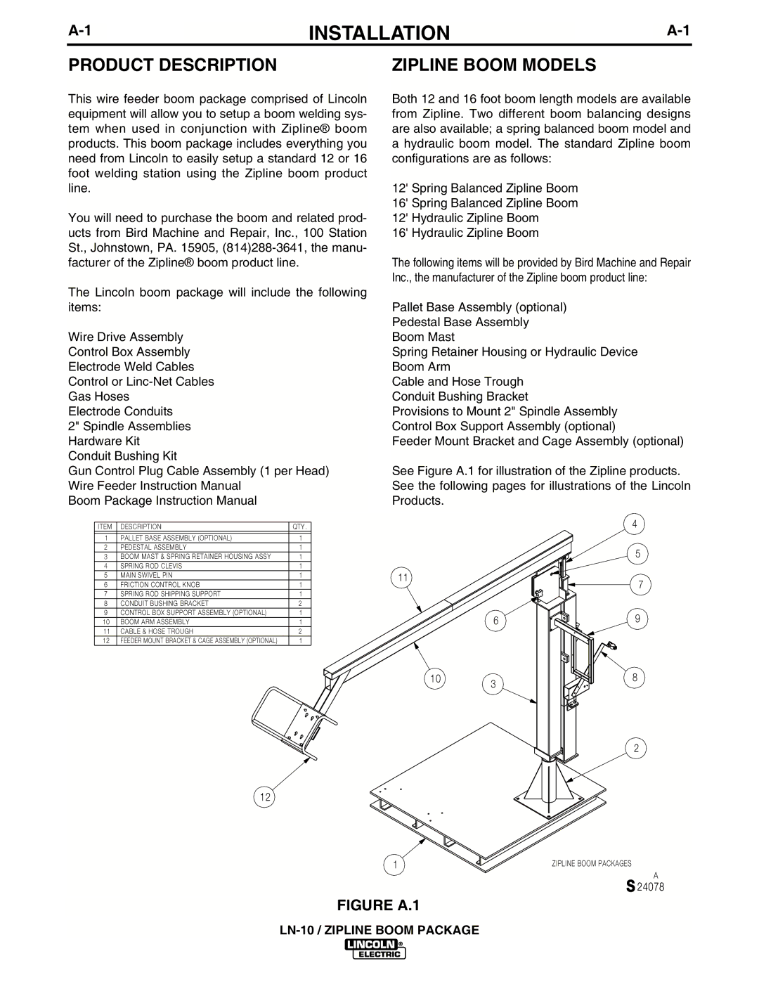
See Figure A.1 for illustration of the Zipline products. See the following pages for illustrations of the Lincoln Products.
ITEM | DESCRIPTION | QTY. |
|
|
1 | PALLET BASE ASSEMBLY (OPTIONAL) | 1 |
|
|
2 | PEDESTAL ASSEMBLY | 1 |
|
|
3 | BOOM MAST & SPRING RETAINER HOUSING ASSY | 1 |
|
|
4 | SPRING ROD CLEVIS | 1 |
|
|
5 | MAIN SWIVEL PIN | 1 | 11 |
|
6 | FRICTION CONTROL KNOB | 1 |
| |
|
| |||
7 | SPRING ROD SHIPPING SUPPORT | 1 |
|
|
8 | CONDUIT BUSHING BRACKET | 2 |
|
|
9 | CONTROL BOX SUPPORT ASSEMBLY (OPTIONAL) | 1 |
| 6 |
10 | BOOM ARM ASSEMBLY | 1 |
| |
11 | CABLE & HOSE TROUGH | 2 |
|
|
12 | FEEDER MOUNT BRACKET & CAGE ASSEMBLY (OPTIONAL) | 1 |
|
|
|
|
| 10 | 3 |
|
|
|
|
12
1
FIGURE A.1
4
5
7
9
8
2
ZIPLINE BOOM PACKAGES
A
S 24078