NOTE: This unit can be vented using only PVC (Class 160, ASTM D-2241; Schedule 40, ASTM D-1785; or Cellular Core Schedule 40 DWV, ASTM F-891), Schedule 40 CPVC/ASTM F-441), or ABS/ASTM D-2661) pipe. The fittings, other than the TERMINATION TEE should be equivalent to PVC-DWV fittings meeting ASTM D-2665 (Use CPVC fittings, ASTM F- 438 for CPVC pipe and ABS fittings, ASTM D-2661/3311 for ABS pipe. If CPVC or ABS pipe and fittings are used, then the proper cement must be used for all joints, including joining the pipe to the Termination Tee (PVC Material). If local codes do not allow the use of the PVC termination when a material other than PVC is used for venting, than an equivalent fitting of that material may be substituted if the screens in the PVC terminal are removed and inserted into the new fitting.

PVC Materials should use ASTM D-2564 Grade Cement; CPVC Materials should use ASTM F-493 Grade Cement and ABS Materials should use ASTM D-2235 Grade Cement.

NOTE: A. For water heaters in locations with high ambient temperatures (above 100°F) and/or insufficient dilution air, it is recommended that CPVC or ABS pipe and fittings be used. B. The SUPPLIED VENT TERMINAL must be used in all cases.

4.The temperature of the flue gases leaving the blower is about 160°F after mixing the dilution air in the inlet adapter of the blower. Even with high concentrate of room air taken into the vent system for dilution air, there will be some installations where condensate will be formed in the horizontal runs of the vent system. This condensate will run into the condensate boot attached to the blower and out the fitting. The water heater is shipped with condensate hose that attaches to the fitting on the condensate boot. No other Tee or fitting is required. See Figures 8 and 9.

INSTALLATION OF VENT SYSTEM

Before beginning installation of piping system thoroughly read the section of this manual VENT PIPE PREPARATION.

If you are installing your system so that it vents through roof, please refer to following section titled INSTALLATION OF VERTICAL VENT SYSTEM.

VENT TERMINAL INSTALLATION, SIDEWALL

1.Install the vent terminal by using the cover plate as a template to mark the hole for the vent pipe to pass through the wall.

BEWARE OF CONCEALED WIRING AND PIPING INSIDE THE WALL.

2.If the Vent Terminal is being installed on the outside of a finished wall, it may be easier to mark both the inside and outside wall. Align the holes by drilling a hole through the center of the template from the inside through to the outside. The template can now be positioned on the outside wall using the drilled hole as a centering point for the template.

3.A) MASONRY SIDE WALLS

Chisel an opening approximately one half inch larger than the marked circle.

B) WOODEN SIDE WALLS

Drill a pilot hole approximately one quarter inch outside of the marked circle. This pilot hole is used as a starting point for a saws-all or sabre saw blade. Cut around the marked circle staying approximately one quarter inch outside of the line. (This will allow the vent to easily slide through the opening. The resulting gap will be covered up by the Vent Terminal cover plate.) Repeat this step on inside wall if necessary.

SEQUENCE OF INSTALLATIONS, FIGURE 5

Cut a length of 3" PVC pipe about 3.5 inches longer than the wall thickness at the opening. Glue the vent terminal "TEE" with screens to this section of pipe. Slide the wall plate over the pipe to stop against "TEE". Place a bead of caulking (not supplied) around the gap between the pipe and cover plate. Apply enough to fill some of the gap between the pipe and wall. Place some of the caulking on the back of the plate to hold it against the wall after installation. If the vent pipe is installed up to the wall, with a coupling on the end against the wall opening, the pipe with the vent terminal can be prepared for gluing before inserting through the wall. Slide the pipe through the wall and insert into the coupling on the other side of the wall, making sure that the vent terminal ends up pointed in the correct position. (See fig. 5).

VENT TERMINATION - FIGURE 5

PREPARATION OF BLOWER ASSEMBLY

1.Check to make sure that the wire harness is attached to the gas valve and blower control box.

2.Make sure no material is still attached to the outside or inside of blower assembly.

MUST INSTALL MINIMUM OF 2" LONG PIECE OF 3" PIPE INTO ELBOW TO MOUNT ON BLOWER DISCHARGE ADAPTER. MAXIMUM LENGTH FOUR

(4) FEET.

FIGURE6

8

Page 8
Image 8
A.O. Smith FPSH - 75 Installation of Vent System, Vent Terminal INSTALLATION, Sidewall, Preparation of Blower Assembly

FPSH - 75 specifications

The A.O. Smith FPSH-75 is a prominent model in the lineup of water heaters offered by A.O. Smith, a company renowned for its innovative approach to water heating solutions. This residential water heater is designed to meet the demands for both efficiency and performance, making it a popular choice for households seeking reliable hot water supply.

One of the standout features of the FPSH-75 is its impressive 75-gallon capacity, which is suitable for larger households or properties that require high volumes of hot water. This feature ensures that multiple fixtures can be used simultaneously without the worry of running out of hot water. Additionally, the unit is equipped with a powerful heating element that provides rapid heating, making it efficient for quick recovery times even during peak usage.

The FPSH-75 utilizes advanced insulation technology to minimize heat loss, which enhances energy efficiency. This means that the water heater can maintain the desired water temperature while consuming less energy. As a result, homeowners can enjoy significant savings on their energy bills, all while benefiting from consistent hot water availability.

This model is also designed with user-friendly controls, allowing homeowners to set and adjust their water temperature preferences easily. The intuitive interface ensures that users can operate the unit without hassle, optimizing their water heating experience.

Safety is also a critical consideration in the design of the FPSH-75. It comes with built-in safety features, including a temperature and pressure relief valve, which helps prevent potential hazards associated with overheating and excessive pressure buildup. Moreover, the durable construction of the tank is engineered to withstand corrosion, extending the lifespan of the water heater.

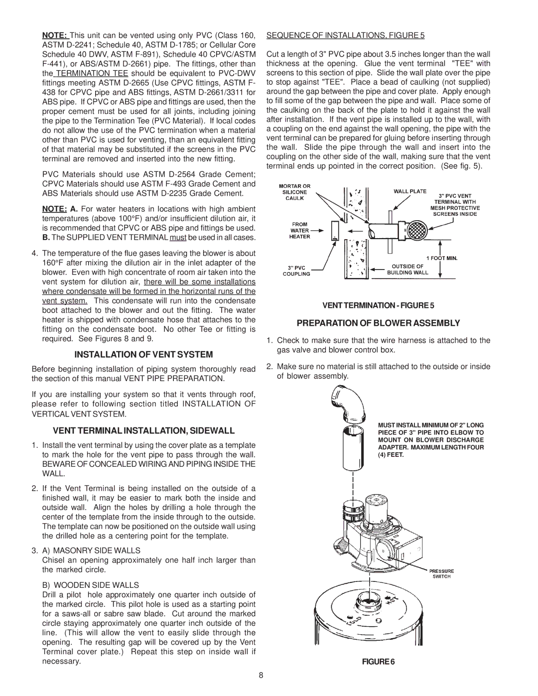
Installation is made convenient with the FPSH-75, as it is compatible with various plumbing setups, making it adaptable for a range of home designs. The model has been certified for meeting the industry standards, ensuring reliability and peace of mind for end-users.

In summary, the A.O. Smith FPSH-75 is an exceptional water heating solution, ideal for families and homes needing robust hot water delivery. Its combination of high capacity, energy efficiency, user-friendly controls, and safety features make it a top contender among residential water heaters, ensuring that homeowners can enjoy comfort and convenience without compromise.