OPERATION | ||
|
|
|
The wire feeder drive roll pressure should be set to a minimum to prevent wire from coming thru the cable when a wire feed stop occurs. The ideal drive roll pressure is set so the drive rolls will slip when the electrode is slightly wavy after a wire feed stop.
ELECTRODES AND EQUIPMENT
The MAGNUM®™ 450WC & 650WC guns and cables have been designed for use with Lincoln
a)Check that the welding power source is on and that the shielding gas supply is set for the proper flow rate.
b)Position electrode over joint. The end of the elec- trode should be slightly off the work.
c)Lower your welding helmet, close the gun trigger, and begin welding. Hold the gun so the contact tip to work distance gives the correct electrical stickout as required for the procedure being used.
d)To stop welding, release the gun trigger and then pull the gun away from the work after the arc goes out.
MAKING A WELD
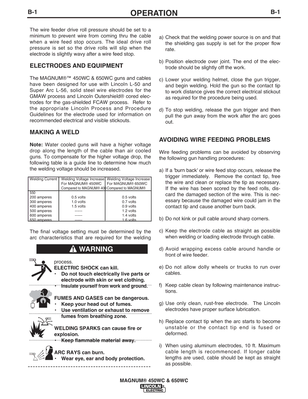
Note: Water cooled guns will have a higher voltage drop along the length of the cable than air cooled guns. To compensate for the higher voltage drop, the following table is a guide line to determine how much the welding voltage should be increased.
Welding Current | Welding Voltage Increase | Welding Voltage Increase |
| For MAGNUM® 450WC | For MAGNUM® 650WC |
| Compared to MAGNUM® | 400Compared to MAGNUM® |
550 |
|
|
200 amperes | 0.5 volts | 0.5 volts |
300 amperes | 1.0 volts | 0.7 volts |
400 amperes | 1.5 volts | 0.9 volts |
500 amperes | 1.2 volts | |
600 amperes | 1.4 volts | |
650 amperes | 1.6 volts |
The final voltage setting must be determined by the arc characteristics that are required for the welding
![]() WARNING
WARNING
process.
ELECTRIC SHOCK can kill.
•Do not touch electrically live parts or electrode with skin or wet clothing.
•Insulate yourself from work and ground.
![]() FUMES AND GASES can be dangerous.
FUMES AND GASES can be dangerous.
• Keep your head out of fumes.
•Use ventilation or exhaust to remove
fumes from breathing zone.
WELDING SPARKS can cause fire or explosion.
•Keep flammable material away.
ARC RAYS can burn.
• Wear eye, ear and body protection.
AVOIDING WIRE FEEDING PROBLEMS
Wire feeding problems can be avoided by observing the following gun handling procedures:
a)If a 'burn back' or wire feed stop occurs, release the trigger immediately. Remove the contact tip, free the wire and clean or replace the tip as necessary. If the wire has been scored by the feed rolls, dis- card the damaged section of the wire. This is nec- essary because the damaged wire could jam in the contact tip and cause another burn back.
b)Do not kink or pull cable around sharp corners.
c)Keep the electrode cable as straight as possible when welding or loading electrode through cable.
d)Avoid wrapping excess cable around handle or front of wire feeder.
e)Do not allow dolly wheels or trucks to run over cables.
f)Keep cable clean by following maintenance instruc- tions.
g)Use only clean,
h)Replace contact tip when the arc starts to become unstable or the contact tip end is fused or deformed.
i)When using aluminum electrodes, 10 ft. Maximum cable length is recommenced. If longer cable lengths are used, cable should be kept as straight as possible.
MAGNUM® 450WC & 650WC
