INSTALLATION | ||
|
|
|
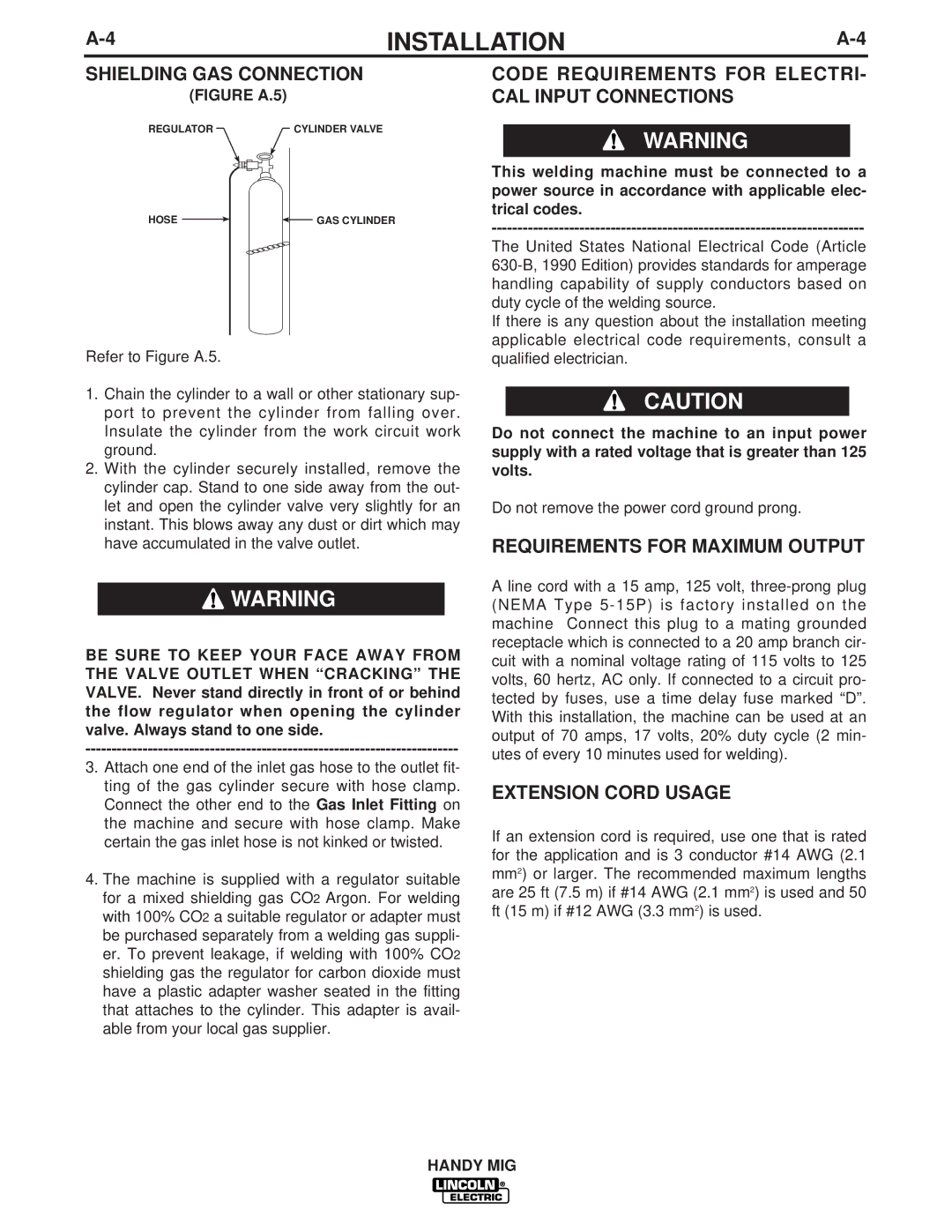
SHIELDING GAS CONNECTION
(FIGURE A.5)
REGULATOR | CYLINDER VALVE |
HOSE |
|
|
| GAS CYLINDER |
|
|
Refer to Figure A.5.
1.Chain the cylinder to a wall or other stationary sup- port to prevent the cylinder from falling over. Insulate the cylinder from the work circuit work ground.
2.With the cylinder securely installed, remove the cylinder cap. Stand to one side away from the out- let and open the cylinder valve very slightly for an instant. This blows away any dust or dirt which may have accumulated in the valve outlet.
![]() WARNING
WARNING
BE SURE TO KEEP YOUR FACE AWAY FROM THE VALVE OUTLET WHEN “CRACKING” THE VALVE. Never stand directly in front of or behind the flow regulator when opening the cylinder valve. Always stand to one side.
3.Attach one end of the inlet gas hose to the outlet fit- ting of the gas cylinder secure with hose clamp. Connect the other end to the Gas Inlet Fitting on the machine and secure with hose clamp. Make certain the gas inlet hose is not kinked or twisted.
4.The machine is supplied with a regulator suitable for a mixed shielding gas CO2 Argon. For welding with 100% CO2 a suitable regulator or adapter must be purchased separately from a welding gas suppli- er. To prevent leakage, if welding with 100% CO2 shielding gas the regulator for carbon dioxide must have a plastic adapter washer seated in the fitting that attaches to the cylinder. This adapter is avail- able from your local gas supplier.
CODE REQUIREMENTS FOR ELECTRI- CAL INPUT CONNECTIONS
WARNING
This welding machine must be connected to a power source in accordance with applicable elec- trical codes.
The United States National Electrical Code (Article
If there is any question about the installation meeting applicable electrical code requirements, consult a qualified electrician.
CAUTION
Do not connect the machine to an input power supply with a rated voltage that is greater than 125 volts.
Do not remove the power cord ground prong.
REQUIREMENTS FOR MAXIMUM OUTPUT
A line cord with a 15 amp, 125 volt,
EXTENSION CORD USAGE
If an extension cord is required, use one that is rated for the application and is 3 conductor #14 AWG (2.1 mm2) or larger. The recommended maximum lengths are 25 ft (7.5 m) if #14 AWG (2.1 mm2) is used and 50 ft (15 m) if #12 AWG (3.3 mm2) is used.