|
|
|
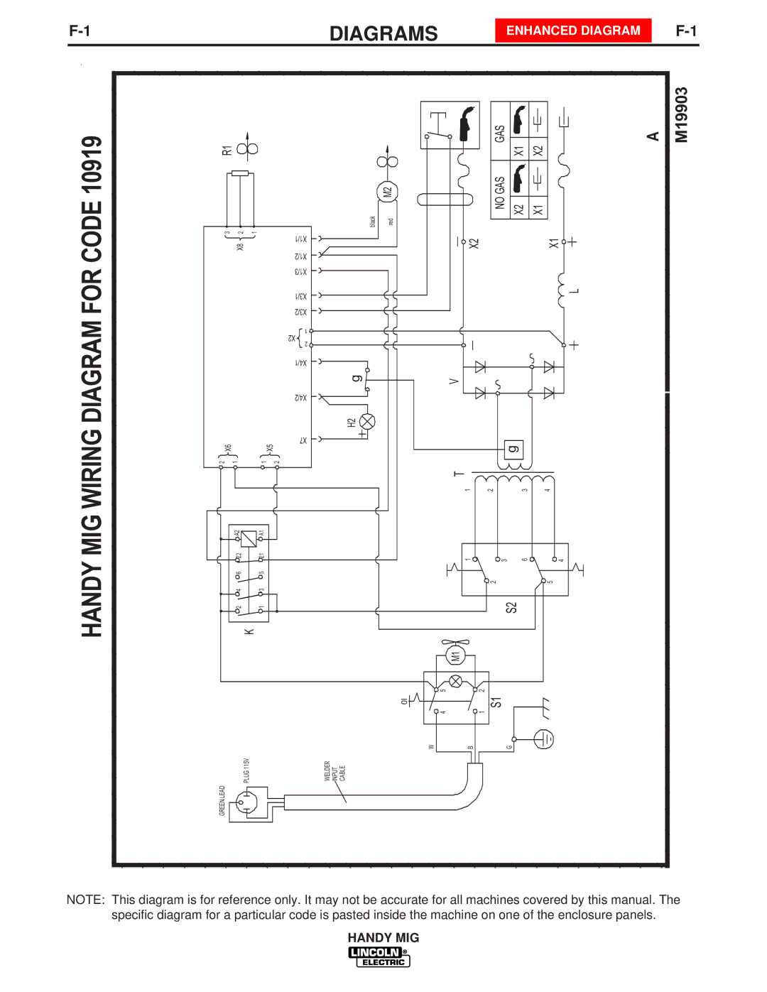
| DIAGRAMS |
|
| ENHANCED DIAGRAM | |||||||
|
|
|
|
|
|
|
|
|
|
| ||||
10919 | R1 |
|
|
|
| M2 |
| GAS GAS | X1 | X2 |
| A | M19903 | |
CODE | 3 | X8 2 | 1 |
| X1/1 | red | X2 | NO | X2 | X1 | X1 |
|
| |
| X1/2 |
|
| |||||||||||
| black |
|
| |||||||||||
FOR |
|
|
|
| X1/3 |
|
|
|
|
|
|
|
|
|
|
|
|
| X3/1 |
|
|
|
|
|
|
| L |
| |
|
|
|
| X3/2 |
|
|
|
|
|
|
|
| ||
DIAGRAM |
|
|
|
| 1 |
|
|
|
|
|
|
|
|
|
|
|
|
| X2 |
|
|
|
|
|
|
|
|
| |
|
|
|
| 2 |
|
|
|
|
|
|
|
|
| |
|
|
|
| X4/1 |
|
|
|
|
|
|
|
|
| |
|
|
|
| g |
| V |
|
|
|
|
|
|
| |
|
|
|
| X4/2 |
|
|
|
|
|
|
|
| ||
|
|
|
| H2 |
|
|
|
|
|
|
|
| ||
WIRING | 2 X6 |
|
| 1 X5 | X7 |
|
|
| g |
|
|
|
|
|
1 |
| 2 |
| T 1 | 2 | 3 |
| 4 |
|
| ||||
MIG |
| A2 |
| 21 A1 |
|
|
|
|
|
|
|
|
|
|
| 22 |
|
|
|
| 3 |
|
|
|
|
| |||
HANDY |
|
|
|
|
|
| 1 | 6 |
|
| 4 |
| ||
| 2 4 6 | K | 1 3 5 |
|
| 2 | S2 |
| 5 |
| ||||
|
|
|
|
|
|
| M1 |
|
|
|
|
|
|
|
|
|
|
|
|
| 5 |
| 2 |
|
|
|
|
|
|
|
|
|
|
|
| 0I |
| S1 |
|
|
|
|
|
|
|
|
|
|
|
| 4 |
| 1 |
|
|
|
|
|
|
|
|
|
|
|
| W | B |
| G |
|
|
|
|
|
| GREEN LEAD |
| PLUG 115V |
| WELDER INPUT CABLE |
|
|
|
|
|
|
|
|
|
|
|
|
|
|
|
|
|
|
|
|
|
|
| |
NOTE: This diagram is for reference only. It may not be accurate for all machines covered by this manual. The specific diagram for a particular code is pasted inside the machine on one of the enclosure panels.