| DIAGRAMS | ||
|
|
|
|
|
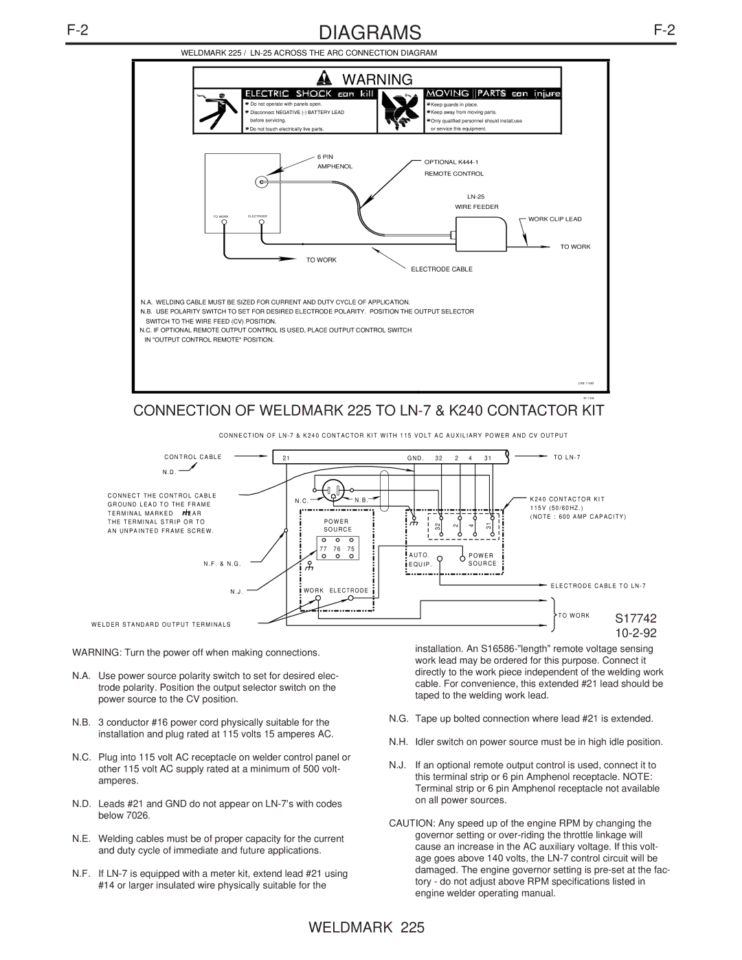
| WELDMARK 225 / |
|
WARNING | |
Do not operate with panels open. | Keep guards in place. |
Disconnect NEGATIVE | Keep away from moving parts. |
before servicing. | Only qualified personnel should install,use |
Do not touch electrically live parts. | or service this equipment. |
6 PIN AMPHENOL
OPTIONAL
TO WORK | ELECTRODE | |
|
|
|
REMOTE CONTROL
WIRE FEEDER
WORK CLIP LEAD
TO WORK
TO WORK
ELECTRODE CABLE
N.A. WELDING CABLE MUST BE SIZED FOR CURRENT AND DUTY CYCLE OF APPLICATION.
N.B. USE POLARITY SWITCH TO SET FOR DESIRED ELECTRODE POLARITY. POSITION THE OUTPUT SELECTOR SWITCH TO THE WIRE FEED (CV) POSITION.
N.C. IF OPTIONAL REMOTE OUTPUT CONTROL IS USED, PLACE OUTPUT CONTROL SWITCH IN "OUTPUT CONTROL REMOTE" POSITION.
CRM 21883
M17486
CONNECTION OF WELDMARK 225 TO LN-7 & K240 CONTACTOR KIT
CONNECTION OF LN - 7 & K240 CONTACTOR KIT WITH 115 VOLT AC AUXILIARY POWER AND CV OUTPUT
CONTROL CABLE
N . D .![]()
CONNECT THE CONTROL CABLE
GROUND LEAD TO THE FRAME
TERMINAL MARKED ![]()
![]()
![]() NEAR
NEAR
THE TERMINAL STRIP OR TO
AN UNPAINTED FRAME SCREW .
N . F . & N . G .
N . J .
WELDER STANDARD OUTPUT TERMINALS
21 |
|
| G N D . | 3 2 |
| 2 4 | 3 1 |
N . C . |
| N . B . |
|
|
|
|
|
POWER |
| 3 2 | 2 | 4 | 3 1 | ||
SOURCE |
| ||||||
|
|
|
|
| |||
77 | 76 | 75 | AUTO . |
|
| POWER | |
|
|
|
|
| |||
|
|
| EQUIP . |
| SOURCE | ||
WORK ELECTRODE
TO LN - 7
K240 CONTACTOR KIT
115V (50/60HZ . )
(NOTE : 600 AMP CAPACITY)
![]() ELECTRODE CABLE TO LN - 7
ELECTRODE CABLE TO LN - 7
TO WORK | S17742 |
| |
|
|
WARNING: Turn the power off when making connections.
N.A. Use power source polarity switch to set for desired elec- trode polarity. Position the output selector switch on the power source to the CV position.
N.B. 3 conductor #16 power cord physically suitable for the installation and plug rated at 115 volts 15 amperes AC.
N.C. Plug into 115 volt AC receptacle on welder control panel or other 115 volt AC supply rated at a minimum of 500 volt- amperes.
N.D. Leads #21 and GND do not appear on
N.E. Welding cables must be of proper capacity for the current and duty cycle of immediate and future applications.
N.F. If
installation. An
N.G. Tape up bolted connection where lead #21 is extended.
N.H. Idler switch on power source must be in high idle position.
N.J. If an optional remote output control is used, connect it to this terminal strip or 6 pin Amphenol receptacle. NOTE: Terminal strip or 6 pin Amphenol receptacle not available on all power sources.
CAUTION: Any speed up of the engine RPM by changing the governor setting or