| OPERATION |
|
|
| ||
|
|
|
|
|
|
|
CASE FRONT CONTROLS |
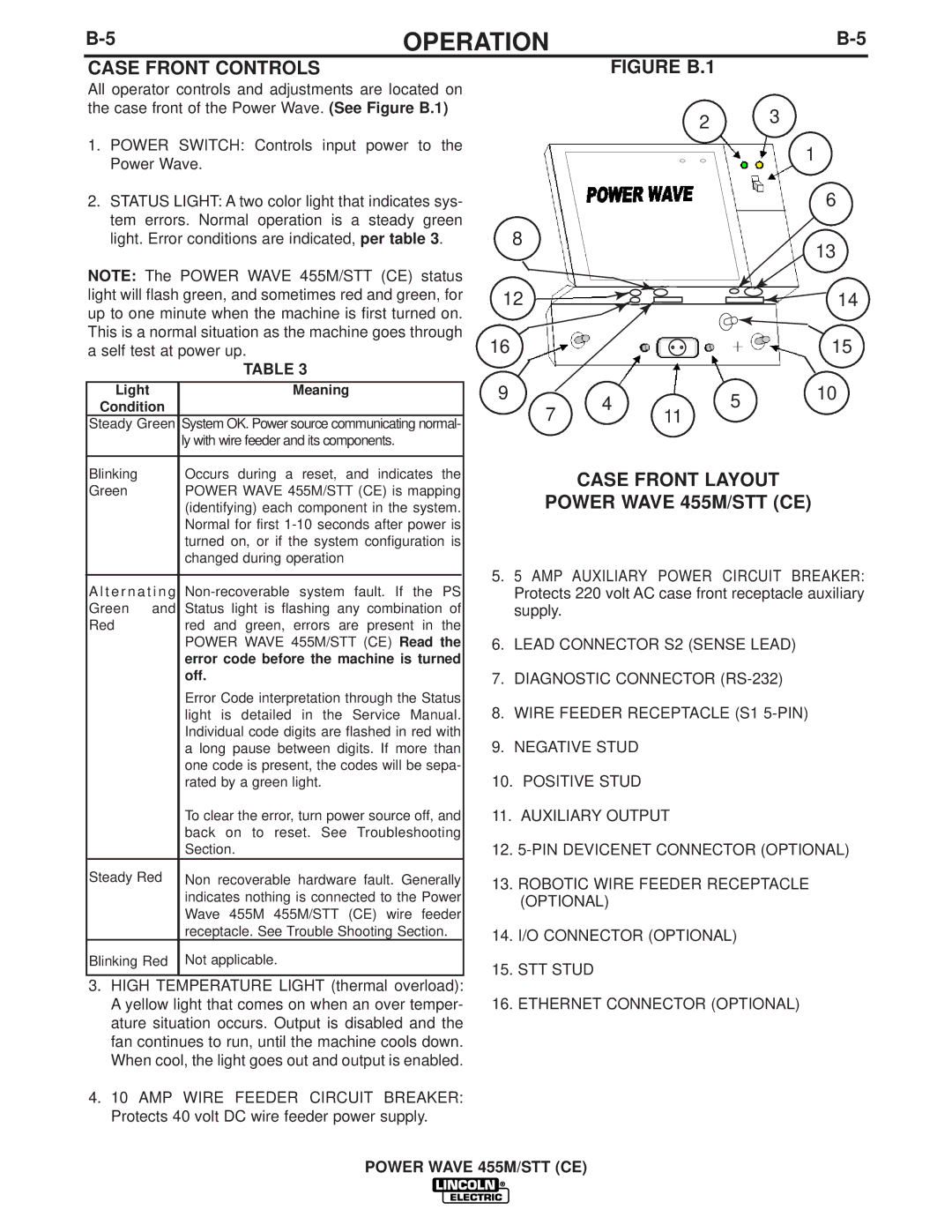
| FIGURE B.1 |
|
| ||
All operator controls and adjustments are located on |
|
|
|
| ||
|
|
|
| |||
the case front of the Power Wave. (See Figure B.1) |
|
|
|
| ||
| 2 | 3 |
| |||
|
|
|
|
| ||
1. POWER | SWITCH: Controls input power to the |
|
|
|
|
|
|
|
|
|
|
|
|
|
|
|
|
|
|
|
|
|
| 1 |
|
| ||||
Power Wave. |
|
|
|
|
|
|
|
|
|
|
|
|
|
|
|
|
|
|
|
|
|
|
|
| ||||||
|
|
|
|
|
|
|
|
|
|
|
|
|
|
|
|
|
|
|
|
|
|
|
| 6 |
| |||||
2. STATUS LIGHT: A two color light that indicates sys- |
|
|
|
|
|
|
|
|
|
|
|
|
|
|
|
|
|
|
|
|
|
|
|
|
| |||||
tem errors. Normal operation is a steady green |
|
| 8 |
|
|
|
|
|
|
|
|
|
|
|
|
|
|
|
|
|
|
|
|
|
|
|
| |||
light. Error conditions are indicated, per table 3. |
|
|
|
|
|
|
|
|
|
|
|
|
|
|
|
|
|
|
|
|
|
|
| 13 |
| |||||
|
|
|
|
|
|
|
|
|
|
|
|
|
|
|
|
|
|
|
|
|
|
|
|
|
|
|
| |||
NOTE: The POWER WAVE 455M/STT (CE) status |
|
|
|
|
|
|
|
|
|
|
|
|
|
|
|
|
|
|
|
|
|
|
|
|
|
|
| |||
|
|
|
|
|
|
|
|
|
|
|
|
|
|
|
|
|
|
|
|
|
|
|
|
|
|
| ||||
light will flash green, and sometimes red and green, for |
| 12 |
|
|
|
|
|
|
|
|
|
|
|
|
|
|
|
|
|
|
|
|
|
| 14 | |||||
|
|
|
|
|
|
|
|
|
|
|
|
|
|
|
|
|
|
|
|
|
|
| ||||||||
|
|
|
|
|
|
|
|
|
|
|
|
|
|
|
|
|
|
|
|
|
| |||||||||
up to one minute when the machine is first turned on. |
|
|
|
|
|
|
|
|
|
|
|
|
|
|
|
|
|
|
|
|
|
|
| |||||||
|
|
|
|
|
|
|
|
|
|
|
|
|
|
|
|
|
|
|
|
|
|
|
|
|
|
| ||||
This is a normal situation as the machine goes through |
| 16 |
|
|
|
|
|
|
|
|
|
|
|
|
|
|
|
|
|
|
|
|
|
| 15 | |||||
a self test at power up. |
|
|
|
|
|
|
|
|
|
|
|
|
|
|
|
|
|
|
|
|
|
|
| |||||||
|
|
|
|
|
|
|
|
|
|
|
|
|
|
|
|
|
|
|
|
|
|
| ||||||||
| TABLE 3 |
|
|
|
|
|
|
|
|
|
|
|
|
|
|
|
|
|
|
|
|
|
|
|
|
|
|
| ||
|
|
|
| 9 |
|
|
|
|
|
|
|
|
|
|
|
|
|
|
|
|
|
|
|
|
|
| 10 |
| ||
Light | Meaning |
|
| 4 |
|
| 5 |
|
|
|
|
|
| |||||||||||||||||
Condition |
|
|
|
| 7 |
|
|
|
|
|
|
|
|
|
|
| ||||||||||||||
|
|
|
|
|
|
|
|
|
| 11 |
|
|
|
|
|
|
|
|
|
|
|
|
|
|
| |||||
Steady Green | System OK. Power source communicating normal- |
|
|
|
|
|
|
|
|
|
| |||||||||||||||||||
| ly with wire feeder and its components. |
|
|
|
|
|
|
|
|
|
|
|
|
|
|
|
|
|
|
|
|
|
|
|
|
|
|
| ||
|
|
|
|
|
|
|
|
|
|
|
|
|
|
|
|
|
|
|
|
|
|
|
|
|
|
|
|
| ||
Blinking | Occurs during a reset, and indicates the |
|
|
|
| CASE FRONT LAYOUT |
|
|
| |||||||||||||||||||||
Green | POWER WAVE 455M/STT (CE) is mapping |
|
|
| POWER WAVE 455M/STT (CE) |
|
|
| ||||||||||||||||||||||
| (identifying) each component in the system. |
|
|
|
|
|
| |||||||||||||||||||||||
| Normal for first |
|
|
|
|
|
|
|
|
|
|
|
|
|
|
|
|
|
|
|
|
|
|
|
|
|
|
| ||
| turned on, or if the system configuration is |
|
|
|
|
|
|
|
|
|
|
|
|
|
|
|
|
|
|
|
|
|
|
|
|
|
|
| ||
| changed during operation |
| 5. 5 AMP AUXILIARY POWER CIRCUIT BREAKER: | |||||||||||||||||||||||||||
|
|
|
| |||||||||||||||||||||||||||
A l t e r n a t i n g | ||||||||||||||||||||||||||||||
|
| Protects 220 volt AC case front receptacle auxiliary | ||||||||||||||||||||||||||||
Green and | Status light is flashing any combination of |
|
| supply. |
|
|
|
|
|
|
|
|
|
|
|
|
|
|
|
|
|
|
|
|
|
|
| |||
Red | red and green, errors are present in the |
|
|
|
|
|
|
|
|
|
|
|
|
|
|
|
|
|
|
|
|
|
|
|
|
|
|
| ||
| POWER WAVE 455M/STT (CE) Read the |
| 6. LEAD CONNECTOR S2 (SENSE LEAD) |
|
|
| ||||||||||||||||||||||||
| error code before the machine is turned |
|
|
|
|
|
|
|
|
|
|
|
|
|
|
|
|
|
|
|
|
|
|
|
|
|
|
| ||
| off. |
| 7. DIAGNOSTIC CONNECTOR |
|
|
| ||||||||||||||||||||||||
| Error Code interpretation through the Status |
| 8. WIRE FEEDER RECEPTACLE (S1 |
|
|
| ||||||||||||||||||||||||
| light is detailed in the Service Manual. |
|
|
|
| |||||||||||||||||||||||||
| Individual code digits are flashed in red with |
| 9. NEGATIVE STUD |
|
|
|
|
|
|
|
|
|
|
|
|
|
|
|
|
|
| |||||||||
| a long pause between digits. If more than |
|
|
|
|
|
|
|
|
|
|
|
|
|
|
|
|
|
|
| ||||||||||
| one code is present, the codes will be sepa- |
| 10. POSITIVE STUD |
|
|
|
|
|
|
|
|
|
|
|
|
|
|
|
|
|
| |||||||||
| rated by a green light. |
|
|
|
|
|
|
|
|
|
|
|
|
|
|
|
|
|
|
| ||||||||||
| To clear the error, turn power source off, and |
| 11. AUXILIARY OUTPUT |
|
|
| ||||||||||||||||||||||||
| back on to reset. See Troubleshooting |
| 12. | |||||||||||||||||||||||||||
| Section. |
| ||||||||||||||||||||||||||||
Steady Red | Non recoverable hardware fault. Generally |
| 13. ROBOTIC WIRE FEEDER RECEPTACLE |
|
|
| ||||||||||||||||||||||||
| indicates nothing is connected to the Power |
|
| (OPTIONAL) |
|
|
|
|
|
|
|
|
|
|
|
|
|
|
|
|
|
| ||||||||
| Wave 455M 455M/STT (CE) wire feeder |
|
|
|
|
|
|
|
|
|
|
|
|
|
|
|
|
|
|
|
|
|
|
|
|
|
|
| ||
| receptacle. See Trouble Shooting Section. |
|
| 14. I/O CONNECTOR (OPTIONAL) |
|
|
| |||||||||||||||||||||||
Blinking Red | Not applicable. |
|
|
| ||||||||||||||||||||||||||
| 15. STT STUD |
|
|
|
|
|
|
|
|
|
|
|
|
|
|
|
|
|
| |||||||||||
|
|
|
|
|
|
|
|
|
|
|
|
|
|
|
|
|
|
|
|
|
| |||||||||
3. HIGH | TEMPERATURE LIGHT (thermal overload): |
| 16. ETHERNET CONNECTOR (OPTIONAL) |
|
|
| ||||||||||||||||||||||||
A yellow light that comes on when an over temper- |
|
|
|
| ||||||||||||||||||||||||||
ature situation occurs. Output is disabled and the |
|
|
|
|
|
|
|
|
|
|
|
|
|
|
|
|
|
|
|
|
|
|
|
|
|
|
| |||
fan continues to run, until the machine cools down. |
|
|
|
|
|
|
|
|
|
|
|
|
|
|
|
|
|
|
|
|
|
|
|
|
|
|
| |||
When cool, the light goes out and output is enabled. |
|
|
|
|
|
|
|
|
|
|
|
|
|
|
|
|
|
|
|
|
|
|
|
|
|
|
| |||
4.10 AMP WIRE FEEDER CIRCUIT BREAKER: Protects 40 volt DC wire feeder power supply.