A-4

INSTALLATION

A-4


3.Be sure the torch and work cable rubber coverings are free of cuts and cracks that allow high frequen- cy leakage. Cables with high natural rubber content, such as Lincoln Stable-Arc® better resist high fre- quency leakage than neoprene and other synthetic rubber insulated cables.

4.Keep the torch in good repair and all connections tight to reduce high frequency leakage.

5.The work terminal must be connected to a ground within ten feet of the welder, using one of the fol- lowing methods:

A metal underground water pipe in direct contact with the earth for ten feet or more.

A 3/4" (19 mm) galvanized pipe or a 5/8" (16 mm) solid galvanized iron, steel or copper rod driven at least eight feet into the ground.

The ground should be securely made and the ground- ing cable should be as short as possible using cable of the same size as the work cable, or larger. Grounding to the building frame electrical conduit or a long pipe system can result in re-radiation, effectively making these members radiating antennas. (This is not rec-

INPUT and GROUNDING CONNECTIONS

WARNING

ELECTRIC SHOCK can kill.

Turn the input power OFF at the disconnect switch or fuse box before working on this equipment.

Be sure the voltage, phase, and frequency of the input power is as specified on the rating plate, located on the rear of the machine.

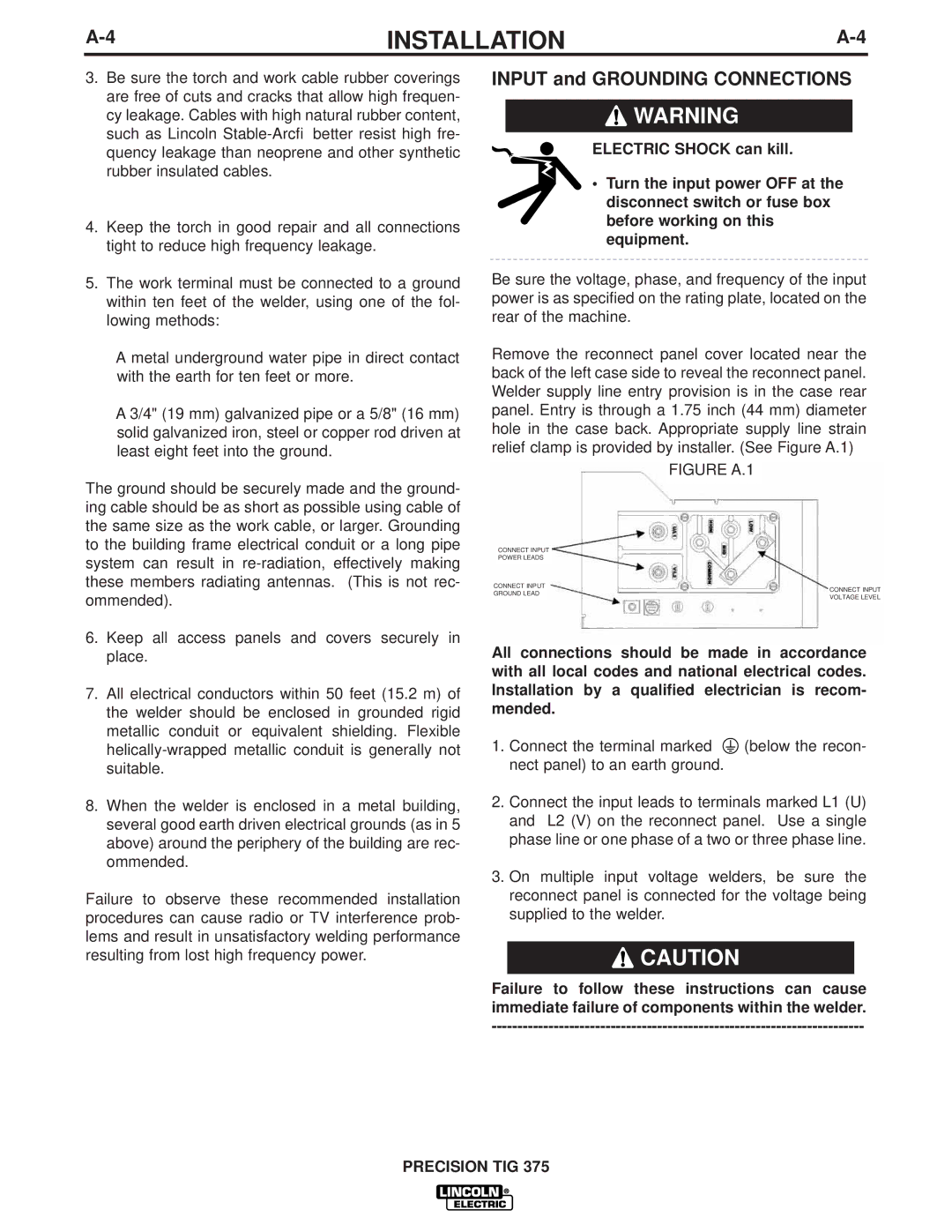
Remove the reconnect panel cover located near the back of the left case side to reveal the reconnect panel. Welder supply line entry provision is in the case rear panel. Entry is through a 1.75 inch (44 mm) diameter hole in the case back. Appropriate supply line strain relief clamp is provided by installer. (See Figure A.1)

FIGURE A.1

CONNECT INPUT

POWER LEADS

CONNECT INPUT

ommended).

GROUND LEAD

CONNECT INPUT

VOLTAGE LEVEL

6.Keep all access panels and covers securely in place.

7.All electrical conductors within 50 feet (15.2 m) of the welder should be enclosed in grounded rigid metallic conduit or equivalent shielding. Flexible helically-wrapped metallic conduit is generally not suitable.

8.When the welder is enclosed in a metal building, several good earth driven electrical grounds (as in 5 above) around the periphery of the building are rec- ommended.

Failure to observe these recommended installation procedures can cause radio or TV interference prob- lems and result in unsatisfactory welding performance resulting from lost high frequency power.

All connections should be made in accordance with all local codes and national electrical codes. Installation by a qualified electrician is recom- mended.

1.Connect the terminal marked (below the recon- nect panel) to an earth ground.

2.Connect the input leads to terminals marked L1 (U) and L2 (V) on the reconnect panel. Use a single phase line or one phase of a two or three phase line.

3.On multiple input voltage welders, be sure the reconnect panel is connected for the voltage being supplied to the welder.

CAUTION

Failure to follow these instructions can cause immediate failure of components within the welder.

------------------------------------------------------------------------

PRECISION TIG 375

Page 13
Image 13
Lincoln Electric IM909 manual Input and Grounding Connections

IM909 specifications

Lincoln Electric IM909 is an innovative industrial multi-process inverter welder designed to provide exceptional flexibility, performance, and user-friendly operation for a wide range of welding applications. This versatile machine is suitable for both novice and experienced welders, making it an ideal choice for workshops, fabrication shops, and maintenance operations.

At the core of the IM909 is its multi-process capability, allowing users to perform MIG, TIG, and stick welding operations. This means that a single machine can cater to various welding needs, from thin sheet metal to heavy structural projects, providing great versatility in welding materials like steel, stainless steel, and aluminum. The IM909 is designed to meet the demands of today’s welding professionals, enabling seamless transitions between different welding processes without sacrificing performance.

One of the standout features of the IM909 is its advanced inverter technology. The inverter design not only makes the welder compact and lightweight but also enhances energy efficiency and improves arc stability. This results in better control over the welding process, leading to higher quality welds with reduced spatter. Additionally, the IM909 boasts a wide output range, allowing it to handle various welding thicknesses effectively.

Another significant characteristic of the IM909 is its user-friendly interface. The machine comes equipped with a digital display that provides clear readouts of current settings, making it easy for users to monitor and adjust parameters on the fly. Moreover, the intuitive controls simplify the setup process, streamlining operations for users of all experience levels.

Safety is always a top priority in welding operations, and the IM909 integrates several protective features, including over-temperature protection and circuit breaker safeguards. These elements ensure the durability of the machine and protect both the welder and the equipment from potential hazards.

In conclusion, the Lincoln Electric IM909 multi-process inverter welder stands out as a reliable, efficient, and adaptable welding solution. Its combination of advanced inverter technology, multi-process capabilities, user-friendly operation, and safety features makes it an excellent investment for any welding professional looking for quality and versatility in their equipment. Whether performing intricate fabrication work or tackling heavy-duty welding tasks, the IM909 delivers exceptional performance across a wide range of applications.