|
|
|
|
| INSTALLATION |
|
|
|
|
| |||||||||||
|
|
|
|
|
|
|
|
|
|
|
|
|
|
|
|
|
|
|
|
|
|
|
|
|
|
|
|
|
|
|
|
|
|
|
|
|
|
|
|
|
|
| |
|
|
|
|
|
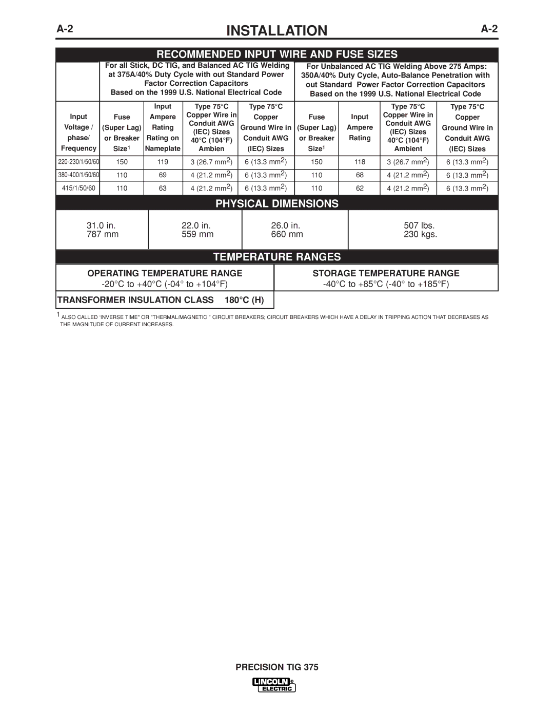
| RECOMMENDED INPUT WIRE AND FUSE SIZES |
|
|
| ||||||||||||
|
|
|
|
|
|
|
|
|
|
|
|
|
|
|
|
|
|
|
|
|
|
|
|
|
| For all Stick, DC TIG, and Balanced AC TIG Welding |
| For Unbalanced AC TIG Welding Above 275 Amps: |
| ||||||||||||||
|
|
|
| at 375A/40% Duty Cycle with out Standard Power |
| 350A/40% Duty Cycle, |
| ||||||||||||||
|
|
|
|
|
| Factor Correction Capacitors |
| out Standard Power Factor Correction Capacitors |
| ||||||||||||
|
|
|
| Based on the 1999 U.S. National Electrical Code |
| Based on the 1999 U.S. National Electrical Code |
| ||||||||||||||
|
|
|
|
|
|
|
|
|
|
|
|
|
|
|
|
|
|
|
|
|
|
|
|
|
|
|
|
|
|
|
|
|
|
|
|
|
|
|
|
|
|
|
|
|
|
|
|
|
|
|
|
|
|
|
|
|
|
|
|
|
|
|
|
| |
|
|
|
|
|
| Input |
| Type 75°C | Type 75°C |
|
|
|
|
|
| Type 75°C |
|
| Type 75°C |
| |
| Input | Fuse |
| Ampere |
| Copper Wire in | Copper |
| Fuse |
|
| Input |
| Copper Wire in |
|
| Copper |
| |||
| Voltage / | (Super Lag) |
| Rating |
| Conduit AWG | Ground Wire in |
| (Super Lag) |
|
| Ampere |
| Conduit AWG |
|
| Ground Wire in |
| |||
| phase/ | or Breaker |
| Rating on |
| (IEC) Sizes | Conduit AWG |
| or Breaker |
|
| Rating |
| (IEC) Sizes |
|
| Conduit AWG |
|
| ||
|
|
| 40°C (104°F) |
|
|
|
| 40°C (104°F) |
|
|
| ||||||||||
| Frequency | Size1 |
| Nameplate |
| Ambien | (IEC) Sizes |
| Size1 |
|
|
|
| Ambient |
|
| (IEC) Sizes |
| |||
| 150 |
| 119 |
| 3 (26.7 mm2) | 6 (13.3 mm2) |
| 150 |
|
| 118 |
| 3 (26.7 mm2) |
|
| 6 (13.3 mm2) |
|
| |||
| 110 |
| 69 |
| 4 (21.2 mm2) | 6 (13.3 mm2) |
| 110 |
|
| 68 |
| 4 (21.2 mm2) |
|
| 6 (13.3 mm2) |
|
| |||
| 415/1/50/60 |
| 110 |
| 63 |
| 4 (21.2 mm2) | 6 (13.3 mm2) |
| 110 |
|
| 62 |
| 4 (21.2 mm2) |
|
| 6 (13.3 mm2) |
|
| |
|
|
|
|
|
|
|
|
|
|
|
|
|
|
|
|
|
|
|
|
|
|
|
|
|
|
|
|
|
|
|
|
|
|
|
|
|
|
|
|
|
|
|
|
|
|
|
|
|
|
|
|
|
|
|
|
|
|
|
|
|
|
|
|
|
|
| Height | Width | PHYSICAL DIMENSIONSepth | Weight |
| |
|
|
|
|
|
|
|
| 31.0 in. | 22.0 in. |
| 26.0 in. | 507 lbs. |
|
| 787 mm | 559 mm |
| 660 mm | 230 kgs. |
|
|
|
|
|
|
|
|
TEMPERATURE RANGES
OPERATING TEMPERATURE RANGE
STORAGE TEMPERATURE RANGE
TRANSFORMER INSULATION CLASS 180°C (H)
1ALSO CALLED ‘INVERSE TIME" OR "THERMAL/MAGNETIC " CIRCUIT BREAKERS; CIRCUIT BREAKERS WHICH HAVE A DELAY IN TRIPPING ACTION THAT DECREASES AS THE MAGNITUDE OF CURRENT INCREASES.
