MAINTENANCE | ||
|
|
|
CONTACT TIP ALIGNMENT
During gooseneck replacement or after a torch colli- sion it may be required to check the contact tip align- ment. If using a robot, it is recommended that a tool center pointer is placed in the robotic cell to define the location of the lead wire. A second locating station should be installed that provides two locating pins that will check the alignment of the lead and trail wire.
If the torch requires maintenance that will effect the alignment of the lead or trail wire placement, the torch should be removed from the robot or hard automation work cell and the
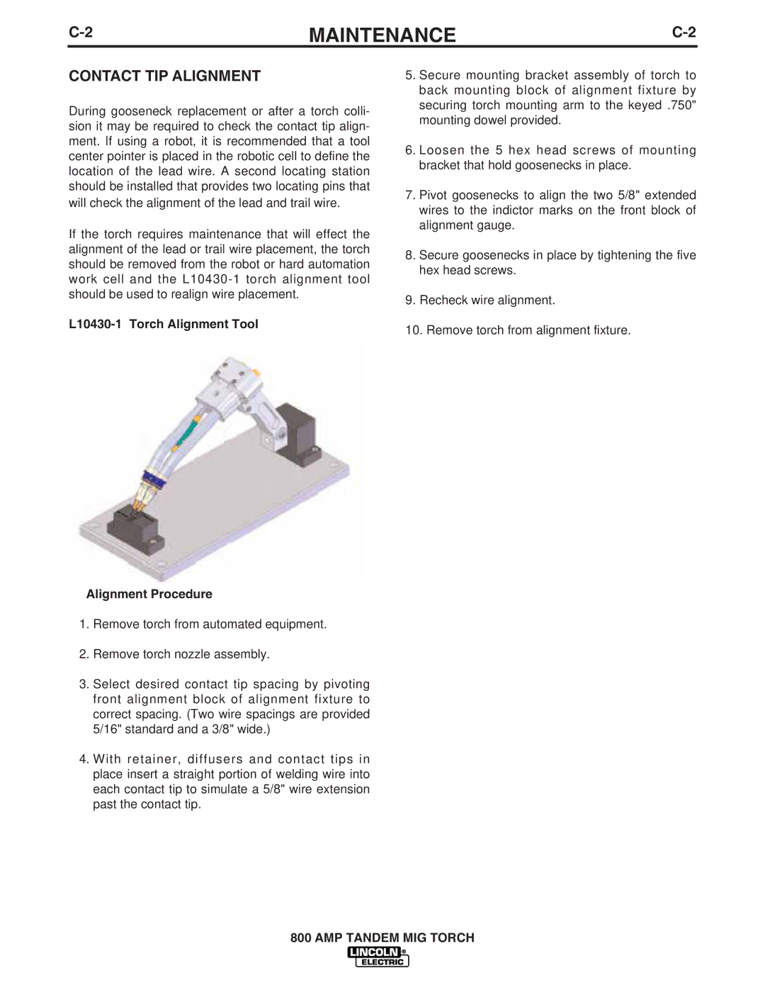
L10430-1 Torch Alignment Tool
Alignment Procedure
1.Remove torch from automated equipment.
2.Remove torch nozzle assembly.
3.Select desired contact tip spacing by pivoting front alignment block of alignment fixture to correct spacing. (Two wire spacings are provided 5/16" standard and a 3/8" wide.)
4.With retainer, diffusers and contact tips in place insert a straight portion of welding wire into each contact tip to simulate a 5/8" wire extension past the contact tip.
5.Secure mounting bracket assembly of torch to back mounting block of alignment fixture by securing torch mounting arm to the keyed .750" mounting dowel provided.
6.Loosen the 5 hex head screws of mounting bracket that hold goosenecks in place.
7.Pivot goosenecks to align the two 5/8" extended wires to the indictor marks on the front block of alignment gauge.
8.Secure goosenecks in place by tightening the five hex head screws.
9.Recheck wire alignment.
10.Remove torch from alignment fixture.
800 AMP TANDEM MIG TORCH