INSTALLATION |
CONNECTION DIAGRAMS
GTAW (TIG) WELDING
A user interface is required for adjusting the TIG weld- ing settings.
SMAW (STICK) WELDING
Similar to TIG welding a user interface is required for adjusting the Stick welding settings. A Power Feed wire feeder can be used as the user interface, or a
GMAW (MIG) WELDING
An arclink compatible wire feeder is recommended for Mig welding. Refer to Figure A.5 for the connection details.
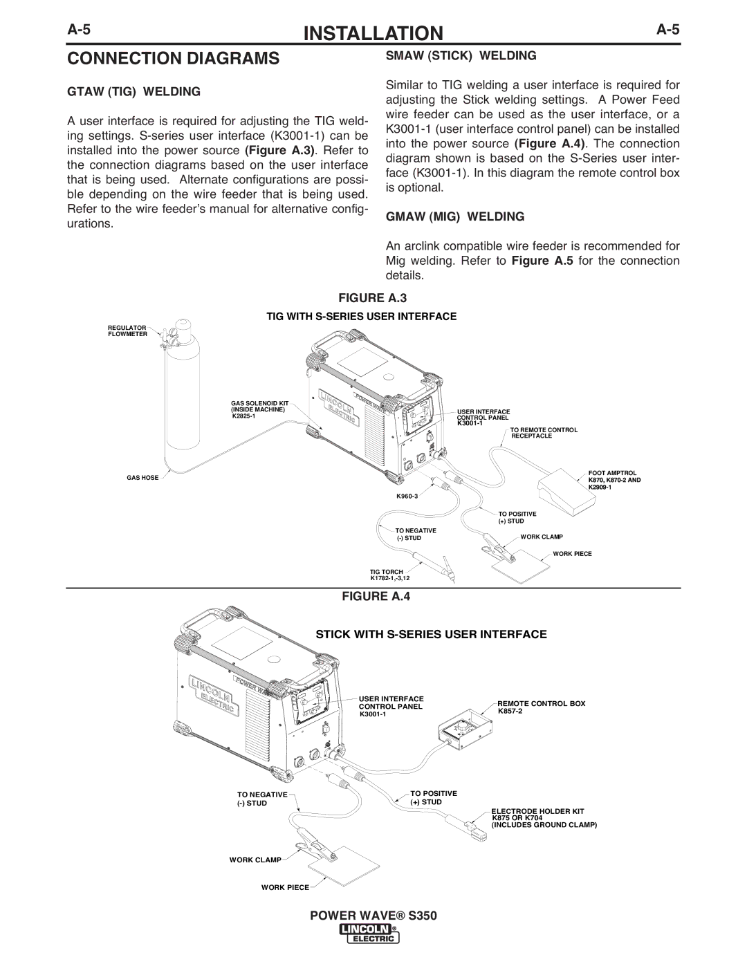
FIGURE A.3
TIG WITH S-SERIES USER INTERFACE
REGULATOR
FLOWMETER
GAS SOLENOID KIT (INSIDE MACHINE)
GAS HOSE ![]()
USER INTERFACE
CONTROL PANEL
TO REMOTE CONTROL
RECEPTACLE
FOOT AMPTROL
K870,
![]() TO POSITIVE
TO POSITIVE ![]()
![]()
(+) STUD
![]() TO NEGATIVE
TO NEGATIVE
WORK CLAMP |
WORK PIECE
TIG TORCH ![]()
FIGURE A.4
STICK WITH S-SERIES USER INTERFACE
TO NEGATIVE
USER INTERFACE
CONTROL PANEL
TO POSITIVE
(+) STUD
REMOTE CONTROL BOX ![]()
ELECTRODE HOLDER KIT K875 OR K704 (INCLUDES GROUND CLAMP)
WORK CLAMP
WORK PIECE
POWER WAVE® S350