Section TOC

Master TOC

G-3

ELECTRICAL DIAGRAMS

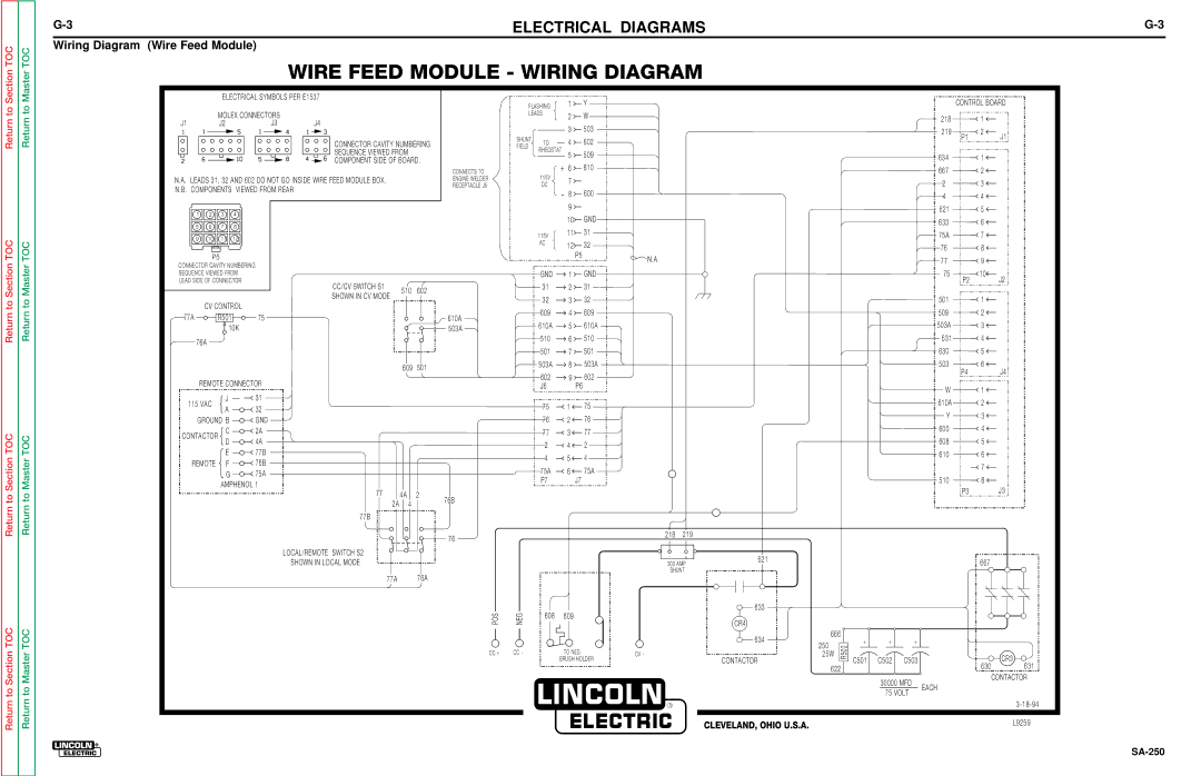
Wiring Diagram (Wire Feed Module)


WIRE FEED MODULE - WIRING DIAGRAM

G-3


ELECTRICAL SYMBOLS PER E1537


MOLEX CONNECTORS


J1

J2

J3

J4

CONNECTOR CAVITY NUMBERING

SEQUENCE VIEWED FROM

COMPONENT SIDE OF BOARD.

N.A. LEADS 31, 32 AND 602 DO NOT GO INSIDE WIRE FEED MODULE BOX.


N.B. COMPONENTS

VIEWED FROM REAR


1

2

3

4


5

6

7

8


9

10

11

12


P5


CONNECTOR CAVITY NUMBERING


SEQUENCE VIEWED FROM


LEAD SIDE OF CONNECTOR


CC/CV SWITCH S1

510

602


SHOWN IN CV MODE


CV CONTROL


77A


R501

75


10K


76A


609

501


REMOTE CONNECTOR


115 VAC

J

31


A

32


GROUND B

GND


CONTACTOR

C

2A


D

4A


E

77B


REMOTE

F

76B


G

75A


AMPHENOL 1


77

4A

2


2A

4


77B

LOCAL/REMOTE SWITCH S2

SHOWN IN LOCAL MODE

77A 76A


FLASHING


1

Y


LEADS


2

W


3

503


SHUNT

TO


4

602


FIELD


RHEOSTAT


5

509


CONNECTS TO


+

6

610


115V


ENGINE WELDER


7


RECEPTACLE J5


DC

-


600


8


9


10

GND


115V


11

31


AC


12

32


P5

N.A.


GND


1

GND


31


2

31


32


3

32


610A


609


4

609


610A


5

610A


503A


510


6

510


501


7

501


503A


8

503A


602


9

602


J6


P6


75


1

75


76


2

76


77


3

77


2


4

2


4


5

4


75A


6

75A


P7


J7


76B


76


218

219


-

+

621


300 AMP


SHUNT


POS

NEG


608

609


633


CR4


634

CC +

CC -


TO NEG

CV -


CONTACTOR


BRUSH HOLDER


666

250

25W

622

R502

CONTROL BOARD

218

1


219

2

J1

P1


6341

6672

23

44

6215

6336

75A7

768

779

75

10

P2

J2

501

1

509

2

503A

3

631

4

630

5

503

6

P4

J4

W

1

610A

2

Y

3

600

4

608

5

6106

7

5108

P3J3

667

+++

C501 C502

C503

CR3


630

631

30000 MFD

CONTACTOR

EACH

75 VOLT


R

CLEVELAND, OHIO U.S.A.

3-18-94

L9259

SA-250

Page 108
Image 108
Lincoln Electric SVM128-A service manual Wire Feed Module Wiring Diagram

SVM128-A specifications

The Lincoln Electric SVM128-A is a cutting-edge welding machine designed to meet the demands of both professional welders and DIY enthusiasts. This versatile welding power source brings together advanced technology and robust design, making it a reliable choice for various welding applications.

One of the standout features of the SVM128-A is its capability to perform multiple welding processes. It supports MIG, TIG, and stick welding, allowing users to tackle a wide range of projects with ease. This multi-functionality makes it ideal for professionals working in different industries, as well as for hobbyists who enjoy diverse welding tasks.

The SVM128-A is equipped with inverter technology, which enhances its performance by providing a more stable arc and improved energy efficiency. This technological advancement contributes to lower operational costs and allows for a more consistent weld quality across different materials and thicknesses. Additionally, the inverter technology enables the machine to be lightweight and portable, making it convenient for jobs that require mobility.

Another prominent characteristic of the SVM128-A is its user-friendly interface. The machine features intuitive controls and a digital display that allows operators to easily set the desired welding parameters. This simplified setup helps reduce the learning curve for new users while also offering precise control for experienced professionals.

The Lincoln Electric SVM128-A is designed with durability in mind. Its robust construction ensures that it can withstand the rigors of frequent use in demanding environments. The machine is also equipped with various safety features, including thermal overload protection and a duty cycle rating that prevents overheating, ultimately extending its lifespan.

For optimal performance, the SVM128-A provides adjustable output options, allowing users to customize the welding parameters based on their specific needs. This flexibility makes it suitable for welding various metals, including steel, aluminum, and stainless steel.

In summary, the Lincoln Electric SVM128-A combines versatility, advanced technology, and a user-friendly design. With its capability to perform multiple welding processes, lightweight construction, and durable features, it stands out as an excellent option for anyone looking to achieve high-quality welds. Whether for professional or personal use, the SVM128-A is poised to deliver reliable performance and exceptional results.