Return to Section TOC

Return to Section TOC

Return to Section TOC

Return to Section TOC

Return to Master TOC

Return to Master TOC

Return to Master TOC

Return to Master TOC

G-2


ELECTRICAL DIAGRAMS


G-2

Wiring Diagram


SA-250 & 350-SA

WIRING DIAGRAM


ELECTRICAL SYMBOLS

CONTROL PANEL COMPONENTS


SHOWN AS VIEWED FROM REAR.


PER E1537


P10


NEUTRAL BONDED TO FRAME


LEAD COLOR CODE

NEUTRE RACCORDE 'AU BATI

12 11 10 9 8

7 6 5

4 3 2 1


THERMOSTART


U


B-BLACK


W


J5


IDLER


G-GREEN


B


+Y


IGNITER


U


N-BROWN


N


P.C.

R


ALTERNATOR

ROTOR


-W


ENGINE


U


BOARD

W


(LEADS APPEAR ON

SLIP RINGS


-


PROTECTION


Y


EARLIER UNITS ONLY)

+


RELAY


B

+

610


53


ENGINE


56A


SLIP RING


IGNITION


IDLER


57


W B

NEAREST


610

602B


HOUR


TO IRON


R

AC


AC

600B


SWITCH


THERMO


METER

FUSE (SFE-14)

SWITCH


IDLER


41


1


START

START

+

-


56


SOLENOID


-


G NO NC S B


115 VOLT


230 VOLT


Y

600A


2


58

59B


OIL PRESSURE


B

RECEPTACLE

RECEPTACLE


15A.

42


3


51B


G


4


59


60


54


SWITCH(N.C.)


FUSE

Y

602A


5


51A

52


RHEOSTAT


6


Y


J8


60A


59C


B


P9


SELECTOR


B


50A


R


SWITCH


FUEL


G


B


INJECTION


ALTERNATOR


.


PUMP


CB2

B


B

CB3

W


CB4


AUXILIARY


TEMPERATURE


CB1


G


POWER


GAUGE


WINDINGS


GENERATOR


50


B


B


G


A


S


+ A -


59A


B


+


ALTERNATOR


B


5 4 3

2 1


STARTING


CURRENT


CR2 REED

WELDER


+ -

EXC


U

TRANSFORMER


MOTOR


51


RELAY

LEAD BLOCK


60B

60D


U


R


N U -W+Y


N


GROUND


POSITIVE


TO BASE


NEGATIVE


(CC-)

(CC+) & (CV+ WITH W.F.M.)


REMOTE CONTROL (OPTIONAL)

PLUG FOR


WIRE FEED MODULE (OPTIONAL)


REMOTE CONTROL RECEPTACLE & SWITCH


REMOTE CONTROL


ON MACHINE, REMOVE PLUG "P10" FROM CONNECTOR "J5".


POTENTIOMETER


CONNECT PLUG "P5" ON W.F.M. TO CONNECTOR "J5" ON MACHINE.


*


SEEBELOW


B


X


Y


X

INLINE


PLUG


R


CONNECTORS


(P5)


.


1

41


W.F.M.


.

*


2

600


Y


CONTROL


SEE


W


PANEL


.

3

42


R


B


BELOW

4

602


G


CONNECT

CONNECT TO POS. & NEG.


POS.

#8

LEAD

WIRE

FEED


CONNECT


5


W


TO CASE


6


TO CASE


OUTPUT TERMINALS


NEG.


MODULE


P8


NEGATIVE CV


#2 HEAVY LEAD


OUTPUT TERMINAL


SWITCH FOR LOCAL OR REMOTE CONTROL


PANEL


608


,


SHOWN IN LOCAL POSITION.


609


* WITH MACHINE NOT RUNNING,


CONNECT TO NEG.


REMOVE PLUG "P9" ON


BRUSH HOLDER


MACHINE FROM CONNECTOR "J8". THEN CONNECT


REMOTE CONTROL


#2 HEAVY LEAD


PLUG "P8" ON REMOTE CONTROL TO


CONNECTOR "J8" ON MACHINE.


POTENTIOMETER BOX


* MACHINE MUST NOT BE RUNNING


THE RED AND BLACK LEADS ARE USED ON CLASSIC I MACHINES ONLY AND ARE NOT


250 AMP


WILL RESULT IF THE RED AND BLACK LEADS ARE CONNECTED IN THE SA-250


THERMOSTAT


CONNECTED ON THIS MACHINE. DAMAGE TO THE REMOTE CONTROL AND/OR MACHINE


WHEN MAKING THESE CONNECTIONS.


AND 350-SA.


ASSEMBLY


R


7-19-96J


CLEVELAND, OHIO U.S.A.


L9150

NOTE: This diagram is for reference only. It may not be accurate for all machines covered by this manual. The wiring diagram specific to your code is pasted inside one of the enclosure panels of your machine.

SA-250

Page 107
Image 107
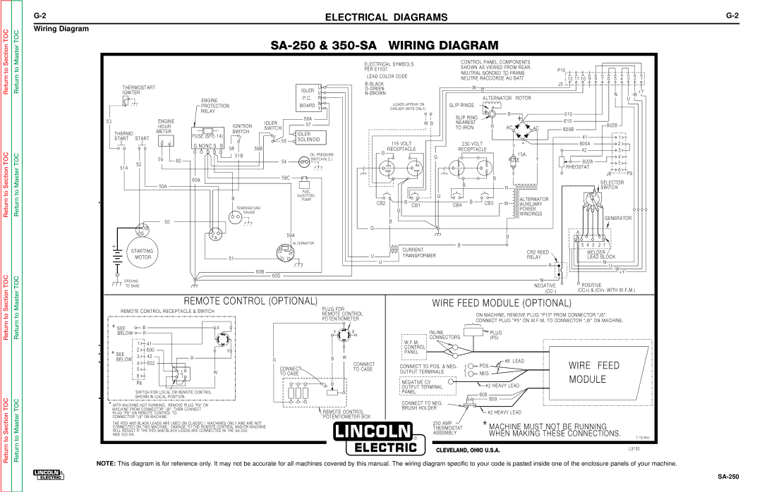
Lincoln Electric SVM128-A service manual Electrical Diagrams, Wiring Diagram

SVM128-A specifications

The Lincoln Electric SVM128-A is a cutting-edge welding machine designed to meet the demands of both professional welders and DIY enthusiasts. This versatile welding power source brings together advanced technology and robust design, making it a reliable choice for various welding applications.

One of the standout features of the SVM128-A is its capability to perform multiple welding processes. It supports MIG, TIG, and stick welding, allowing users to tackle a wide range of projects with ease. This multi-functionality makes it ideal for professionals working in different industries, as well as for hobbyists who enjoy diverse welding tasks.

The SVM128-A is equipped with inverter technology, which enhances its performance by providing a more stable arc and improved energy efficiency. This technological advancement contributes to lower operational costs and allows for a more consistent weld quality across different materials and thicknesses. Additionally, the inverter technology enables the machine to be lightweight and portable, making it convenient for jobs that require mobility.

Another prominent characteristic of the SVM128-A is its user-friendly interface. The machine features intuitive controls and a digital display that allows operators to easily set the desired welding parameters. This simplified setup helps reduce the learning curve for new users while also offering precise control for experienced professionals.

The Lincoln Electric SVM128-A is designed with durability in mind. Its robust construction ensures that it can withstand the rigors of frequent use in demanding environments. The machine is also equipped with various safety features, including thermal overload protection and a duty cycle rating that prevents overheating, ultimately extending its lifespan.

For optimal performance, the SVM128-A provides adjustable output options, allowing users to customize the welding parameters based on their specific needs. This flexibility makes it suitable for welding various metals, including steel, aluminum, and stainless steel.

In summary, the Lincoln Electric SVM128-A combines versatility, advanced technology, and a user-friendly design. With its capability to perform multiple welding processes, lightweight construction, and durable features, it stands out as an excellent option for anyone looking to achieve high-quality welds. Whether for professional or personal use, the SVM128-A is poised to deliver reliable performance and exceptional results.