Ranger TM300 D and 300 DLX
Safety Depends on You
California Proposition 65 Warnings
Safety
Electric Shock can kill
Welding Sparks can cause fire or explosion
Précautions DE Sûreté
Ranger 300 D and 300 DLX
Master Table of Contents for ALL Sections
Table of Contents Installation Section
Technical Specifications Ranger 300 D and 300 DLX
Installation
Stacking
Safety Precautions
Location and Ventilation
Storing
PRE-OPERATION Engine Service
Engine Coolant
Battery Connections
Gases from Battery can explode
Fuel
Electrical Connections
Remote Control
High Frequency Generators for TIG Applications
Welding Terminals
Total Combined Length of Electrode and Work Cables
Auxiliary Power RECEPTACLES, PLUGS, and HAND-HELD Equipment
Welding Cable Connections
Table A.1
Premises Wiring
Figure A.2 Connection of Ranger 300 to Premises Wiring
Ranger 300 D and 300 DLX
Table of Contents Operation Section
Operation
Safety Instructions
Operating Instructions
General Description
Design Features ALL Models
For Auxiliary Power
Other Features
Ranger 300 D K1522-1
Additional Features
WELDER/GENERATOR Controls
Controls and Settings
Operation
Figure B.2 Engine Controls
Engine Controls
Operation
Before Starting the Engine
Engine Operation
Stopping the Engine
Cold Weather Starting and Operation
BREAK-IN Period
Welding Operation
Welding
AC/DC TIG Constant Current
Pure EWP Range Appropriate Tungsten Diameter Switch Settings
DC Wire Feed Welding CV with Ranger 300 DLX
Electrode Wire Speed Approximate
DC Wire Feed Welding CV with Ranger 300 D
Summary of Welding Processes and Machine Settings
Summary of Welding Processes and Machine Settings
Simultaneous Welding and Power Loads
Auxiliary Power
Duplex Receptacles
120/240 V Dual Voltage Receptacle
Table of Contents Accessories
TIG Welding Options Accessories
General Options Accessories
ING Terminals Always on
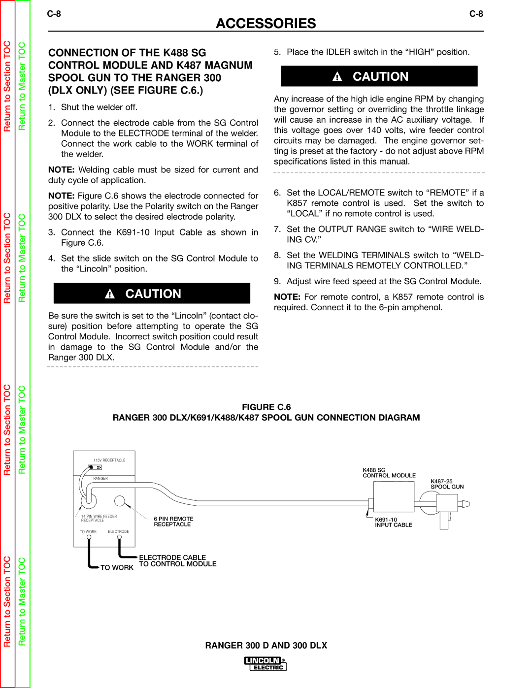
Connection of Lincoln Electric Wire Feeders
PIN
Remotely Controlled
ING Terminals Remotely Controlled
To Work
Return
Ranger 300 D and 300 DLX
Ranger 300 D and 300 DLX
Table of Contents Maintenance
Frequency
Safety Precautions Kubota Engine Maintenance Schedule
Engine Maintenance
Maintenance
Routine and Periodic
Fuel Feedfuel Feedpumppumplever
To prevent Electrical Damage when
Battery Maintenance
Charging the Battery
Welder / Generator Maintenance
Figure D.3 Major Component Locations
Ranger 300 D and 300 DLX
Table of Contents Theory of Operation Section
PROTECTION, ROTOR, Stator
BATTERY, STARTER, Engine
Theory of Operation
Glow PLUGS, Engine
Rotor Field FEEDBACK, Auxiliary and Wire Feeder Power
Figure E-4 Weld WINDING, Reactor and Range Switch
Weld WINDING, Reactor and Range Switch
Return to
Ranger 300 D and 300 DLX
Table of Contents Troubleshooting & Repair Section
HOW to USE Troubleshooting Guide
Troubleshooting & Repair
PC Board Troubleshooting Procedures
Output Problems
Troubleshooting Guide
On page F-6
Output Problems
Field Winding Voltage Test
Troubleshooting Guide
No DC welding output. AC welding Make sure the polarity mode
Troubleshooting & Repair
Volts is normal. If 12VDC is
Engine Problems
Symptoms Misadjustments Course of Action
Problems Possible Areas
High Speed Solenoid Resistance Test
Perform the Fuel Shutdown
Shutdown Solenoid Resis
Function Problems
Perform the Auxiliary
12VDC is
Nections at the battery
Battery does not stay charged Check for loose or faulty con
Engine charging system
Welding Problems
Test Description
Rotor Resistance Test
Materials Needed
Rotor Resistance Test
Test Procedure
Conduct the test with the engine OFF
Output Rectifier Bridge Test
Conduct this test with the engine off
Output Rectifier Bridge Test
Fuel Shutdown Solenoid Resistance Test
Figure F.3 Plug J12 Location
Fuel Shutdown Solenoid Resistance Test
High Speed Solenoid Test
High Speed Solenoid Test
Engine Throttle Adjustment Test
Conduct this procedure with the engine OFF
Engine Throttle Adjustment Test
Figure F.7 High Idle Adjustment
Oscilloscope Method
Frequency Counter Method
Auxiliary and Field Winding Test
To test the 115 VAC winding
Auxiliary and Field Winding Test
To test the 230 VAC winding
To test the field winding
To test the feeder winding Ranger 300 DLX Models
Figure F.11 14-PIN Amphenol PIN Assignments
Rotor Voltage Test
Rotor Voltage Test
Test Procedure
Charging Circuit Test
Charging Circuit Test
Alternator Test Procedure
Normal Open Circuit Voltage Waveform 115VAC Supply
Scope Settings
High Idle no Load Output Control AT Maximum
Machine Loaded
Typical DC Weld Output Voltage Waveform CV Mode High TAP
Machine Loaded to 250 Amps AT 30VDC
Machine Loaded to 250 Amps AT 25 VDC
Typical DC Weld Output Voltage Waveform
Machine Loaded to 250 Amps AT 25VDC
Typical AC Weld Output Voltage Waveform
Abnormal Open Circuit DC Weld Voltage Waveform
Abnormal Open Circuit Weld Voltage Waveform High CV Mode
Normal Open Circuit Weld Voltage Waveform High CV Mode
Normal Open Circuit DC Weld Voltage Waveform
Normal Open Circuit AC Weld Voltage Waveform
Description
Brush Removal and Replacement
Procedure
Brush Removal and Replacement
Section TOC
Field Capacitor AND/OR Rectifier Bridge Removal Replacement
Field Capacitor AND/OR Rectifier Bridge Removal
Replacement
To Section TOC
Control Board Removal and Replacement
Figure F.16 Printed Circuit Board Location
Control Board Removal and Replacement
To Section TOC
Output Rectifier Bridge Removal Replacement
Figure F.17 Output Rectifier Connections
Output Rectifier Bridge Removal and Replacement
Reassembly
Description
Ranger 300 DLX only
Output Capacitor Bank Removal and Replacement
Output Contactor Removal and Replacement Ranger 300 DLX only
Figure F.19 Output Contactor Location
Output Contactor Removal and Replacement
Troubleshooting & REPAIRs
Stator AND/OR Rotor Removal and Replacement
Figure F.21 Component LOCATIONS, STATOR/ROTOR Removal
Stator AND/OR Removal and Replacement
Stator Removal Procedure
Rotor Removal Procedure
Stator AND/OR Rotor Removal and Replacement
Lead Reconnection Checklist Engine
Reassembly Notes
Front Panel
Retest After Repair
Electrical Diagrams
R I N G D I a G R a M R a N G E R 3 0 0 D
Wiring Diagram Ranger 300 D Code
R I N G D I a G R a M R a N G E R 3 0 0 D L
Wiring Diagram Ranger 300 DLX Code
Wiring Diagram Ranger 300 DLX
Schematic Control PC Board
PC Board Assembly Control Board
Schematic Bypass PC Board
PC Board Assembly Bypass Board
SVM Error Reporting Form