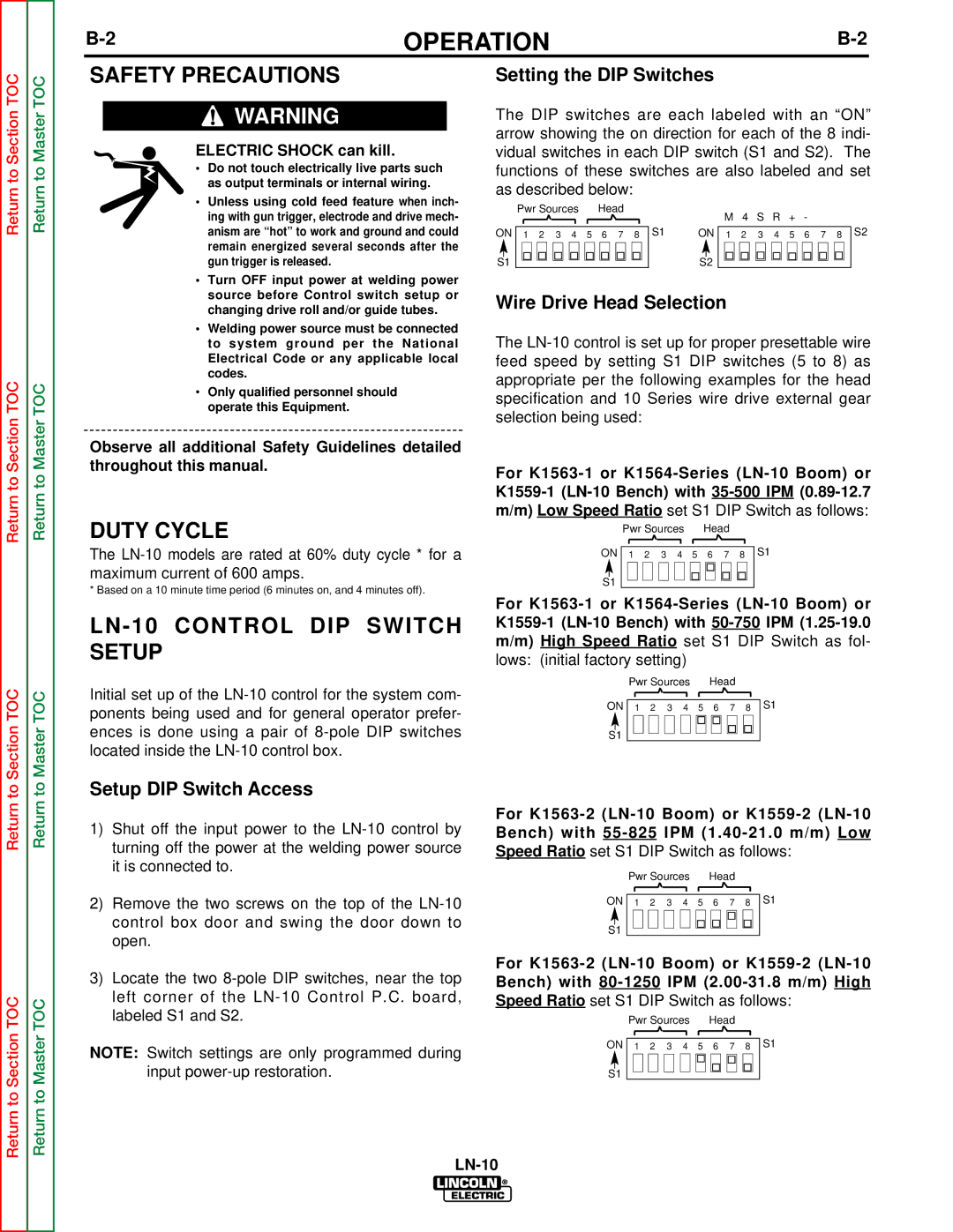
SVM154-A specifications
The Lincoln Electric SVM154-A is a powerful and versatile inverter-based welding machine designed for a wide range of applications. As a part of Lincoln Electric's esteemed portfolio, this model is particularly favored for its robust performance and cutting-edge technologies, making it ideal for both professional fabricators and hobbyists alike.One of the standout features of the SVM154-A is its compact and lightweight design, which enhances portability without compromising power. Weighing significantly less than traditional welding machines, it allows welders to easily transport the equipment to various job sites. This feature is particularly beneficial in industries where mobility is essential.
Equipped with advanced inverter technology, the SVM154-A delivers a stable and smooth arc, providing consistent welding performance even in challenging conditions. The inverter design also contributes to energy efficiency, allowing users to save on operational costs while enjoying superior performance. The machine supports both MIG and TIG welding processes, which adds to its versatility. This adaptability makes it suitable for a range of materials including mild steel, stainless steel, and aluminum.
Another notable characteristic is its user-friendly interface. Designed with the welder in mind, the SVM154-A includes intuitive controls that simplify settings adjustments and operational processes. This ergonomic layout allows for ease of use, even for beginners, while still offering the adjustments that experienced welders appreciate for customizing their welds.
The SVM154-A also includes several safety features, such as thermal overload protection and a dynamic power control, ensuring safe operation while maintaining high productivity. Users benefit from features that protect both the machine and the operator, making it a reliable choice for long hours of work.
Moreover, Lincoln Electric's commitment to durability is evident in the SVM154-A's construction. Built with high-quality materials, this welding machine is designed to withstand the rigors of daily use, ensuring longevity and reliability over time.
In summary, the Lincoln Electric SVM154-A stands out for its portability, versatility, and user-centric design. With advanced inverter technology that promotes energy efficiency and a stability for various welding processes, it serves as a valuable tool for both professionals and hobbyists seeking to achieve high-quality welds across different applications. Its combination of advanced features, safety mechanisms, and rugged durability positions the SVM154-A as a top choice in the welding equipment market.

