INSTALLATION | ||
|
|
|
The following Lincoln engine drives meet these condi- tions when run in the high idle mode:
•Ranger 250,305
•Commander 300, 400, & 500
Many engine drives do not meet these conditions (eg Miller Bobcats, etc). Operation of the Invertec
OUTPUT CONNECTIONS
![]() WARNING
WARNING
ELECTRIC SHOCK can kill.
•Keep the electrode holder and cable insulation in good condition.
•Do not touch electrically live parts or electrode with skin or wet cloth- ing.
•Insulate yourself from work and ground.
•Turn the input line Switch on the Invertec V160- S “off” before connecting or disconnecting out- put cables or other equipment.
The Work Cable and Electrode Cable are supplied with the welder. To connect the cables,turnthe Power Switch “OFF”.
OUTPUT AND GAS CONNECTION FOR TIG WELDING (FIGURE A.1)
FIGURE A.1
GAS HOSE NOZZLE
TIG TORCH
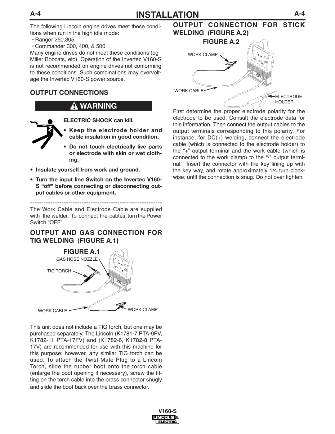
OUTPUT CONNECTION FOR STICK WELDING (FIGURE A.2)
FIGURE A.2
WORK CLAMP ![]()
WORK CABLE ![]()
![]()
![]()
![]()
![]() ELECTRODE
ELECTRODE
HOLDER
First determine the proper electrode polarity for the electrode to be used. Consult the electrode data for this information. Then connect the output cables to the output terminals corresponding to this polarity. For instance, for DC(+) welding, connect the electrode cable (which is connected to the electrode holder) to the “+” output terminal and the work cable (which is connected to the work clamp) to the
WORK CABLE | WORK CLAMP |
This unit does not include a TIG torch, but one may be purchased separately. The Lincoln