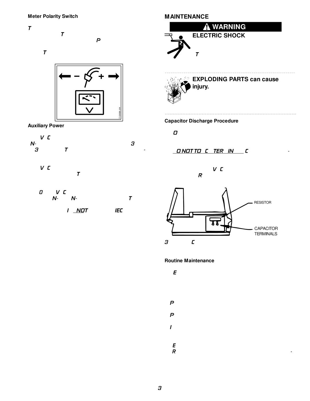
Meter Polarity Switch
The wire feeder polarity switch is located at the rear of the machine. The switch provides a work connection for wire feeder voltmeters. Place the switch in the position of the electrode polarity indicated by the decal. The switch does not change the welding polarity.
T 1 3 0 8 6 - 8 4
Auxiliary Power
A 24 VAC @ 1 amp supply is included for use with the
A 42 VAC @ 5.5 amp supply is included for use with other wire feeders. This supply is protected by a 6 amp breaker located on the rear of the machine.
A 110/115 VAC @ 2 amp supply is included for use with the
All three supplies are not to be loaded simultaneously.
MAINTENANCE
![]() WARNING
WARNING
ELECTRIC SHOCK can kill.
•Have an electrician install and service this equipment.
•Turn the input power off at the fuse box before working on equipment.
•Do not touch electrically hot parts.


 EXPLODING PARTS can cause
injury.
• Failed parts can explode or cause other parts to explode when power is applied.
•Always wear a face shield and long sleeves when servicing.
Capacitor Discharge Procedure
1.Obtain a power resistor (25 ohms, 25 watts).
2.Hold resistor body with electrically insulated glove. DO NOT TOUCH TERMINALS. Connect the resis- tor terminals across the two hex head cap screws in the position shown. Hold in each position for 1 second. For 575 VAC only, repeat for second capacitor. Repeat for the capacitor(s) on the other side of the machine
RESISTOR
CAPACITOR
TERMINALS
3.Use a DC voltmeter to check that voltage is not present across either capacitor.
Routine Maintenance
1.Every 6 months or so the machine should be cleaned with a low pressure airstream. Keeping the machine clean will result in cooler operation and higher reliability. Be sure to clean these areas:
•Power, switch, driver, protection and control printed circuit boards.
•Power switch
•Main transformer
•Input rectifier (located in front of fan blade)
•Heat sink fins
2.Examine the sheet metal case for dents or breakage. Repair the case as required. Keep the case in good con- dition to insure that high voltage parts are protected and correct spacings are maintained. All external sheet metal screws must be in place to insure case strength and electrical ground continuity.
–13 –