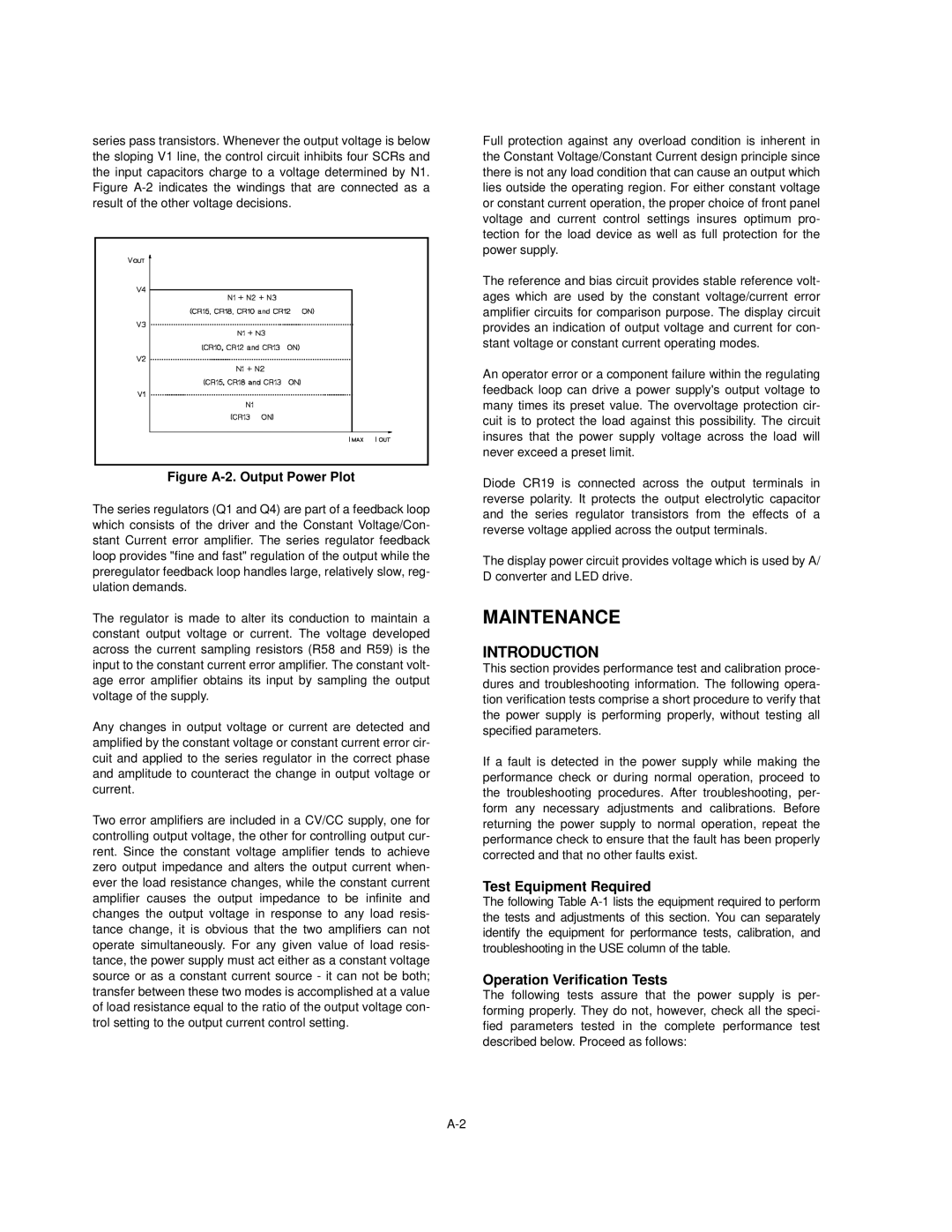
series pass transistors. Whenever the output voltage is below the sloping V1 line, the control circuit inhibits four SCRs and the input capacitors charge to a voltage determined by N1. Figure
Figure A-2. Output Power Plot
The series regulators (Q1 and Q4) are part of a feedback loop which consists of the driver and the Constant Voltage/Con- stant Current error amplifier. The series regulator feedback loop provides "fine and fast" regulation of the output while the preregulator feedback loop handles large, relatively slow, reg- ulation demands.
The regulator is made to alter its conduction to maintain a constant output voltage or current. The voltage developed across the current sampling resistors (R58 and R59) is the input to the constant current error amplifier. The constant volt- age error amplifier obtains its input by sampling the output voltage of the supply.
Any changes in output voltage or current are detected and amplified by the constant voltage or constant current error cir- cuit and applied to the series regulator in the correct phase and amplitude to counteract the change in output voltage or current.
Two error amplifiers are included in a CV/CC supply, one for controlling output voltage, the other for controlling output cur- rent. Since the constant voltage amplifier tends to achieve zero output impedance and alters the output current when- ever the load resistance changes, while the constant current amplifier causes the output impedance to be infinite and changes the output voltage in response to any load resis- tance change, it is obvious that the two amplifiers can not operate simultaneously. For any given value of load resis- tance, the power supply must act either as a constant voltage source or as a constant current source - it can not be both; transfer between these two modes is accomplished at a value of load resistance equal to the ratio of the output voltage con- trol setting to the output current control setting.
Full protection against any overload condition is inherent in the Constant Voltage/Constant Current design principle since there is not any load condition that can cause an output which lies outside the operating region. For either constant voltage or constant current operation, the proper choice of front panel voltage and current control settings insures optimum pro- tection for the load device as well as full protection for the power supply.
The reference and bias circuit provides stable reference volt- ages which are used by the constant voltage/current error amplifier circuits for comparison purpose. The display circuit provides an indication of output voltage and current for con- stant voltage or constant current operating modes.
An operator error or a component failure within the regulating feedback loop can drive a power supply's output voltage to many times its preset value. The overvoltage protection cir- cuit is to protect the load against this possibility. The circuit insures that the power supply voltage across the load will never exceed a preset limit.
Diode CR19 is connected across the output terminals in reverse polarity. It protects the output electrolytic capacitor and the series regulator transistors from the effects of a reverse voltage applied across the output terminals.
The display power circuit provides voltage which is used by A/ D converter and LED drive.
MAINTENANCE
INTRODUCTION
This section provides performance test and calibration proce- dures and troubleshooting information. The following opera- tion verification tests comprise a short procedure to verify that the power supply is performing properly, without testing all specified parameters.
If a fault is detected in the power supply while making the performance check or during normal operation, proceed to the troubleshooting procedures. After troubleshooting, per- form any necessary adjustments and calibrations. Before returning the power supply to normal operation, repeat the performance check to ensure that the fault has been properly corrected and that no other faults exist.
Test Equipment Required
The following Table
Operation Verification Tests
The following tests assure that the power supply is per- forming properly. They do not, however, check all the speci- fied parameters tested in the complete performance test described below. Proceed as follows: