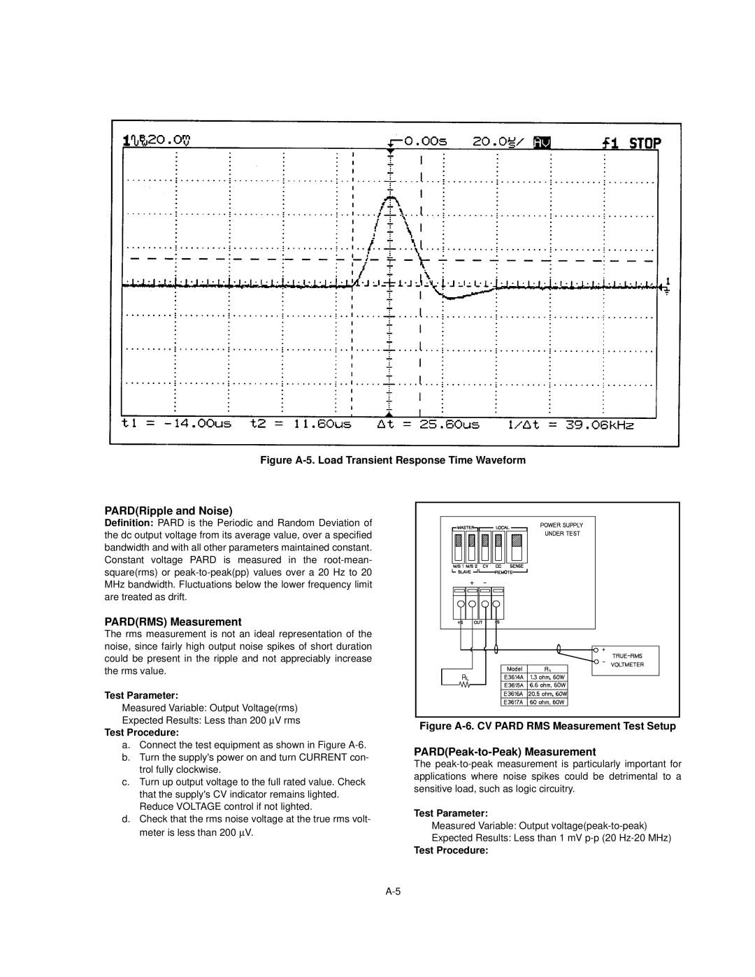
Figure A-5. Load Transient Response Time Waveform
PARD(Ripple and Noise)
Definition: PARD is the Periodic and Random Deviation of the dc output voltage from its average value, over a specified bandwidth and with all other parameters maintained constant. Constant voltage PARD is measured in the
PARD(RMS) Measurement
The rms measurement is not an ideal representation of the noise, since fairly high output noise spikes of short duration could be present in the ripple and not appreciably increase the rms value.
Test Parameter:
Measured Variable: Output Voltage(rms)
Expected Results: Less than 200 μV rms
Test Procedure:
a.Connect the test equipment as shown in Figure
b.Turn the supply's power on and turn CURRENT con- trol fully clockwise.
c.Turn up output voltage to the full rated value. Check that the supply's CV indicator remains lighted. Reduce VOLTAGE control if not lighted.
d.Check that the rms noise voltage at the true rms volt- meter is less than 200BμV.
Figure A-6. CV PARD RMS Measurement Test Setup
PARD(Peak-to-Peak) Measurement
The
Test Parameter:
Measured Variable: Output
Expected Results: Less than 1 mV