LOAD CONSIDERATIONS
This section provides information on operating your supply with various types of loads connected to its output.
PULSE LOADING
The power supply will automatically cross over from constant- voltage to constant current operation in response to an increase (over the preset limit) in the output current. Although the preset limit may be set higher than the average output current, high peak currents (as occur in pulse loading) may exceed the preset cur- rent limit and cause cross over to occur. If this cross over limiting is not desired, set the preset limit for the peak requirement and not the average.
REVERSE CURRENT LOADING
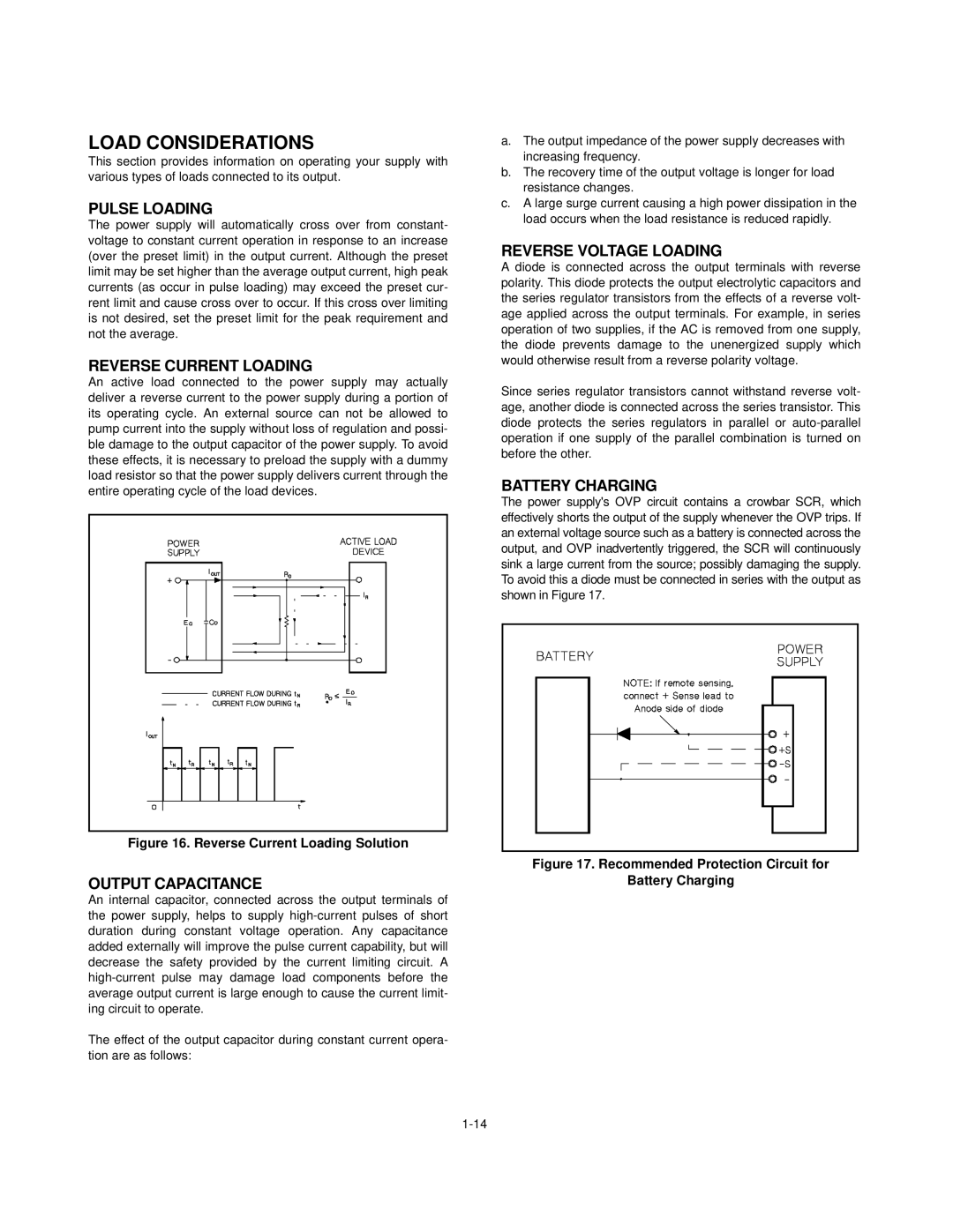
An active load connected to the power supply may actually deliver a reverse current to the power supply during a portion of its operating cycle. An external source can not be allowed to pump current into the supply without loss of regulation and possi- ble damage to the output capacitor of the power supply. To avoid these effects, it is necessary to preload the supply with a dummy load resistor so that the power supply delivers current through the entire operating cycle of the load devices.
Figure 16. Reverse Current Loading Solution
OUTPUT CAPACITANCE
An internal capacitor, connected across the output terminals of the power supply, helps to supply
The effect of the output capacitor during constant current opera- tion are as follows:
a.The output impedance of the power supply decreases with increasing frequency.
b.The recovery time of the output voltage is longer for load resistance changes.
c.A large surge current causing a high power dissipation in the load occurs when the load resistance is reduced rapidly.
REVERSE VOLTAGE LOADING
A diode is connected across the output terminals with reverse polarity. This diode protects the output electrolytic capacitors and the series regulator transistors from the effects of a reverse volt- age applied across the output terminals. For example, in series operation of two supplies, if the AC is removed from one supply, the diode prevents damage to the unenergized supply which would otherwise result from a reverse polarity voltage.
Since series regulator transistors cannot withstand reverse volt- age, another diode is connected across the series transistor. This diode protects the series regulators in parallel or
BATTERY CHARGING
The power supply's OVP circuit contains a crowbar SCR, which effectively shorts the output of the supply whenever the OVP trips. If an external voltage source such as a battery is connected across the output, and OVP inadvertently triggered, the SCR will continuously sink a large current from the source; possibly damaging the supply. To avoid this a diode must be connected in series with the output as shown in Figure 17.