Manuals
/
Agilent Technologies
/
Computer Equipment
/
Power Supply
Agilent Technologies
E3615A, E3614A, E3617A, E3616A
service manual
Models:
E3615A
E3614A
E3616A
E3617A
1
35
47
47
Download
47 pages
24.48 Kb
32
33
34
35
36
37
38
39
Troubleshooting
Install
Connecting Loads
Maintenance
TURN-ON Checkout Procedure
Resolution
Safety
Service Information
Constant Voltage Mode
Page 35
Image 35
Page 34
Page 36
Page 35
Image 35
Page 34
Page 36
Contents
April
Agilent E361xA 60W Bench Series DC Power Supplies
Safety Summary
Operating Instructions
General Information
Line Fuse
Operating Temperature Range
Meter Programming Resolution
Temperature Coefficient
Initial Inspection
Installation
Installation Data
Input Power Requirements
Operating Instructions
TURN-ON Checkout Procedure
Power Cord
Operation Beyond Rated Output
Local Operating Mode
Connecting Loads
Operating Modes
Remote Analog Voltage Programming
Remote Operating Modes
Remote Voltage Sensing
AUTO-PARALLEL Operation
MULTIPLE-SUPPLY Operation
Normal Parallel Operation
Gramming according to the remote-programming instructions
Normal Series Operation
Total output voltage to ground must not exceed 240 Vdc
AUTO-SERIES Operation
= slave output voltage
AUTO-TRACKING Operaton
Load Considerations
Service Information
Operation Verification Tests
Maintenance
Test Equipment Required
Measurement Techniques
Type Required Characteristics USE Recommended Model
Performance Tests
Load Transient Response Time
Constant Voltage CV Tests
Load Regulation Load Effect
Line Regulation Source Effect
PARDPeak-to-Peak Measurement
PARDRipple and Noise
Pardrms Measurement
CV Drift Stability
Constant Current CC Tests
CC Drift Stability
Adjustment and Calibration Procedure
Regulating Loop Troubles
Troubleshooting
Overall Troubleshooting Procedure
Reference and Bias Circuit
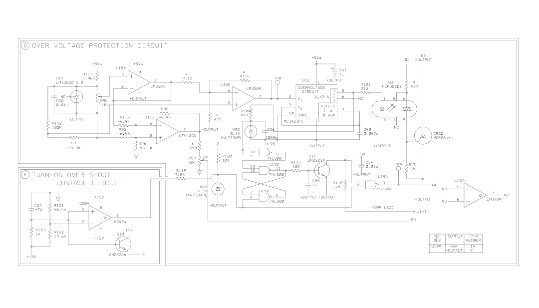
Overvoltage Protection Circuit Troubles
Symptom Checks and Probable Causes
Step Action Response Probable Cause
Step Measure Response Probable Cause
Replaceable Parts
Table A-10. Replaceable Parts List
Table A-10. Replaceable Parts List Contd
R28,111 0698-3228 Resistor 49.9K +-1% .125W TF TC=0+-100
RESISTOR-VAR 10K +-10% ALL
IC V RGLTR-FXD-POS 4.8/5.2V TO-220 PKG ALL
DIODE-GEN PRP 180V 200MA DO-35 ALL
Table A-11. Component Value Model
Page
Page
Page
Page
Manual Supplement
T E
Constant Voltage Mode
Programming Voltage Common to the Minus Output
Alternative Voltage Programming Using Resistors
Programming Voltage Common to the Minus Output
Constant Current with Voltage Programming
Constant Current Mode
Current Monitoring
Remote Resistor Programming, Constant Voltage
Remote Resistor Programming Connections
Remote Resistor Programming, Constant Current
Certification
Declaration of Conformity
Top
Page
Image
Contents