Table
STEP | ACTION |
| RESPONSE |
| PROBABLE CAUSE |
|
|
|
| ||
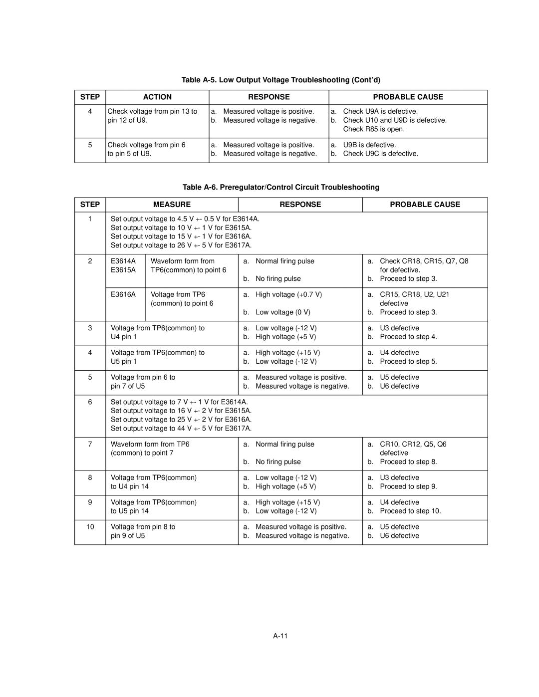
4 | Check voltage from pin 13 to | a. Measured voltage is positive. | a. Check U9A is defective. | ||
| pin 12 of U9. | b. | Measured voltage is negative. | b. Check U10 and U9D is defective. | |
|
|
|
|
| Check R85 is open. |
|
|
|
|
| |
5 | Check voltage from pin 6 | a. Measured voltage is positive. | a. | U9B is defective. | |
| to pin 5 of U9. | b. | Measured voltage is negative. | b. | Check U9C is defective. |
|
|
|
|
|
|
Table
STEP |
|
| MEASURE |
| RESPONSE |
| PROBABLE CAUSE |
|
|
|
|
| |||
1 | Set output voltage to 4.5 V +- 0.5 V for E3614A. |
|
| ||||
| Set output voltage to 10 V +- 1 V for E3615A. |
|
|
| |||
| Set output voltage to 15 V +- 1 V for E3616A. |
|
|
| |||
| Set output voltage to 26 V +- 5 V for E3617A. |
|
|
| |||
|
|
|
|
|
| ||
2 | E3614A |
| Waveform form from | a. | Normal firing pulse | a. Check CR18, CR15, Q7, Q8 | |
| E3615A |
| TP6(common) to point 6 |
|
|
| for defective. |
|
|
|
| b. | No firing pulse | b. Proceed to step 3. | |
|
|
|
|
|
|
| |
| E3616A |
| Voltage from TP6 | a. | High voltage (+0.7 V) | a. CR15, CR18, U2, U21 | |
|
|
| (common) to point 6 |
|
|
| defective |
|
|
|
| b. Low voltage (0 V) | b. Proceed to step 3. | ||
|
|
|
|
|
|
| |
3 | Voltage from TP6(common) to | a. | Low voltage | a. | U3 defective | ||
| U4 pin 1 |
| b. | High voltage (+5 V) | b. Proceed to step 4. | ||
|
|
|
|
|
| ||
4 | Voltage from TP6(common) to | a. | High voltage (+15 V) | a. | U4 defective | ||
| U5 pin 1 |
| b. | Low voltage | b. Proceed to step 5. | ||
|
|
|
|
|
| ||
5 | Voltage from pin 6 to | a. | Measured voltage is positive. | a. | U5 defective | ||
| pin 7 of U5 |
| b. | Measured voltage is negative. | b. | U6 defective | |
|
|
|
|
|
| ||
6 | Set output voltage to 7 V +- 1 V for E3614A. |
|
|
| |||
| Set output voltage to 16 V +- 2 V for E3615A. |
|
|
| |||
| Set output voltage to 25 V +- 2 V for E3616A. |
|
|
| |||
| Set output voltage to 44 V +- 5 V for E3617A. |
|
|
| |||
|
|
|
|
| |||
7 | Waveform form from TP6 | a. | Normal firing pulse | a. CR10, CR12, Q5, Q6 | |||
| (common) to point 7 |
|
|
| defective | ||
|
|
|
| b. | No firing pulse | b. Proceed to step 8. | |
|
|
|
|
|
| ||
8 | Voltage from TP6(common) | a. | Low voltage | a. | U3 defective | ||
| to U4 pin 14 |
| b. | High voltage (+5 V) | b. Proceed to step 9. | ||
|
|
|
|
|
| ||
9 | Voltage from TP6(common) | a. | High voltage (+15 V) | a. | U4 defective | ||
| to U5 pin 14 |
| b. | Low voltage | b. Proceed to step 10. | ||
|
|
|
|
|
| ||
10 | Voltage from pin 8 to | a. | Measured voltage is positive. | a. | U5 defective | ||
| pin 9 of U5 |
| b. | Measured voltage is negative. | b. | U6 defective | |
|
|
|
|
|
|
|
|