REMOTE OPERATING MODES
Remote operating modes discussed below are remote voltage sensing and remote voltage programming. You can set up the unit for remote operating modes by changing the settings of the rear panel switch and connecting the leads from the rear panel termi- nals to the load or the external voltage. Solid conductors of 0.75 to 1.5 mm2 can be connected to the rear panel terminals by sim- ply push fitting. Thinner wires or conductors are inserted into the connection space after depressing the orange opening lever.
Turn off the supply while making changes to rear panel switch settings or connections. This avoids the possibility of damage to the load and OVP shutdown from unin- tended output.
Remote Voltage Sensing
Remote voltage sensing is used to maintain good regulation at the load and reduce the degradation of regulation that would occur due to the voltage drop in the leads between the power supply and the load. By connecting the supply for remote voltage sensing, voltage is sensed at the load rather than at the supply's output terminals. This will allow the supply to automatically com- pensate for the voltage drop in the load leads and improve regula- tion.
When the supply is connected for remote sensing, the OVP circuit senses the voltage at the sense leads and not the main output terminals.
Remote voltage sensing compensates for a voltage drop of up to 0.5 V in each load, and there may be up to a 0.1 V drop between the output terminal and the internal sensing resistor, at which point the OVP circuit is connected. There- fore, the voltage sensed by the OVP circuit could be as much as 1.1 V more than the voltage being regulated at the load. It may be necessary to
CV Regulation. Notice that any voltage drop in the sense leads adds directly to the CV load regulation. In order to maintain the specified performance, keep the sense lead resistance to 0.5 ohms per lead or less.
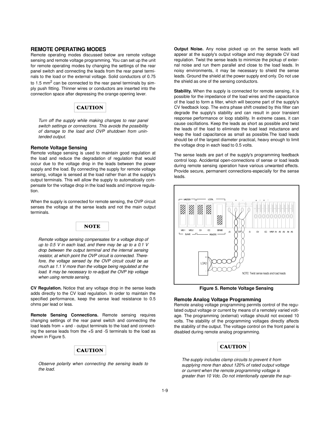
Remote Sensing Connections. Remote sensing requires changing settings of the rear panel switch and connecting the load leads from + and - output terminals to the load and connect- ing the sense leads from the +S and
Observe polarity when connecting the sensing leads to the load.
Output Noise. Any noise picked up on the sense leads will appear at the supply's output voltage and may degrade CV load regulation. Twist the sense leads to minimize the pickup of exter- nal noise and run them parallel and close to the load leads. In noisy environments, it may be necessary to shield the sense leads. Ground the shield at the power supply end only. Do not use the shield as one of the sensing conductors.
Stability. When the supply is connected for remote sensing, it is possible for the impedance of the load wires and the capacitance of the load to form a filter, which will become part of the supply's CV feedback loop. The extra phase shift created by this filter can degrade the supply's stability and can result in poor transient response performance or loop stability. In extreme cases, it can cause oscillations. Keep the leads as short as possible and twist the leads of the load to eliminate the load lead inductance and keep the load capacitance as small as possible.The load leads should be of the largest diameter practical, heavy enough to limit the voltage drop in each lead to 0.5 volts.
The sense leads are part of the supply's programming feedback control loop. Accidental
MASTER |
| LOCAL |
| + | _ | + | _ | + | _ |
|
|
|
| |
M/S 1 | M/S 2 | CV | CC | SENSE | OUT | CV |
| CC | VREF A1 | A2 | A3 | A4 | A5 | |
|
|
|
| +S |
| |||||||||
SLAVE |
| REMOTE |
|
|
|
|
|
|
|
|
|
|
| |
|
| + |
|
|
|
|
|
|
|
|
|
|
|
|
|
| nqcf |
|
|
|
|
|
|
|
|
|
|
|
|
|
| _ |
|
|
|
|
|
|
|
|
|
|
|
|
|
|
|
|
|
|
|
| |||||||
Figure 5. Remote Voltage Sensing
Remote Analog Voltage Programming
Remote analog voltage programming permits control of the regu- lated output voltage or current by means of a remotely varied volt- age. The programming (external) voltage should not exceed 10 volts. The stability of the programming voltages directly affects the stability of the output. The voltage control on the front panel is disabled during remote analog programming.
The supply includes clamp circuits to prevent it from supplying more than about 120% of rated output voltage or current when the remote programming voltage is greater than 10 Vdc. Do not intentionally operate the sup-