|
| Table |
|
|
|
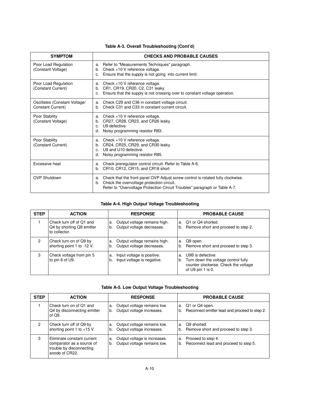
SYMPTOM |
| CHECKS AND PROBABLE CAUSES |
|
|
|
Poor Load Regulation | a. | Refer to "Measurements Techniques" paragraph. |
(Constant Voltage) | b. | Check +10 V reference voltage. |
| c. | Ensure that the supply is not going into current limit. |
|
|
|
Poor Load Regulation | a. | Check +10 V reference voltage. |
(Constant Current) | b. | CR1, CR19, CR20, C2, C31 leaky. |
| c. Ensure that the supply is not crossing over to constant voltage operation. | |
|
|
|
Oscillates (Constant Voltage/ | a. | Check C29 and C36 in constant voltage circuit. |
Constant Current) | b. | Check C31 and C33 in constant current circuit. |
|
|
|
Poor Stability | a. | Check +10 V reference voltage. |
(Constant Voltage) | b. | CR27, CR28, CR23, and CR26 leaky. |
| c. | U9 defective. |
| d. Noisy programming resistor R83. | |
|
|
|
Poor Stability | a. | Check +10 V reference voltage. |
(Constant Current) | b. | CR24, CR25, CR29, and CR30 leaky. |
| c. U9 and U10 defective. | |
| d. Noisy programming resistor R85. | |
|
|
|
Excessive heat | a. | Check preregulator control circuit. Refer to Table |
| b. CR10, CR12, CR15, and CR18 short | |
|
|
|
OVP Shutdown | a. | Check that the front panel OVP Adjust screw control is rotated fully clockwise. |
| b. Check the overvoltage protection circuit. | |
|
| Refer to "Overvoltage Protection Circuit Troubles" paragraph or Table |
|
|
|
Table
STEP | ACTION |
| RESPONSE |
| PROBABLE CAUSE |
|
|
|
| ||
1 | Check turn off of Q1 and | a. Output voltage remains high. | a. Q1 or Q4 shorted. | ||
| Q4 by shorting Q9 emitter | b. | Output voltage decreases. | b. | Remove short and proceed to step 2. |
| to collector. |
|
|
|
|
|
|
|
|
| |
2 | Check turn on of Q9 by | a. Output voltage remains high. | a. | Q9 open. | |
| shorting point 1 to | b. | Output voltage decreases. | b. Remove short and proceed to step 3. | |
|
|
|
|
| |
3 | Check voltage from pin 5 | a. Input voltage is positive. | a. | U9B is defective. | |
| to pin 6 of U9. | b. | Input voltage is negative. | b. Turn down the voltage control fully | |
|
|
|
|
| counter clockwise. Check the voltage |
|
|
|
|
| of U9 pin 1 is 0. |
|
|
|
|
|
|
Table
STEP | ACTION |
| RESPONSE |
| PROBABLE CAUSE |
|
|
|
| ||
1 | Check turn on of Q1 and | a. Output voltage remains low. | a. Q1 or Q4 open. | ||
| Q4 by disconnecting emitter | b. | Output voltage increases. | b. | Reconnect emitter lead and proceed to step 2. |
| of Q9. |
|
|
|
|
|
|
|
|
| |
2 | Check turn off of Q9 by | a. Output voltage remains low. | a. | Q9 shorted. | |
| shorting point 1 to +15 V. | b. | Output voltage increases. | b. Remove short and proceed to step 3. | |
|
|
|
| ||
3 | Eliminate constant current | a. Output voltage is increases. | a. Proceed to step 4. | ||
| comparator as a source of | b. | Output voltage remains low. | b. | Reconnect lead and proceed to step 5. |
| trouble by disconnecting |
|
|
|
|
| anode of CR22. |
|
|
|
|
|
|
|
|
|
|