be grounded or the power supply can be operated float- ing at up to a maximum of 240 Volts off ground. Total out- put voltage to ground must not exceed 240 Vdc.
LINE FUSE |
|
|
Line Voltage | Fuse | Agilent Part No. |
100/115 Vac | 2.0 AT | |
230 Vac | 1.0 AT |
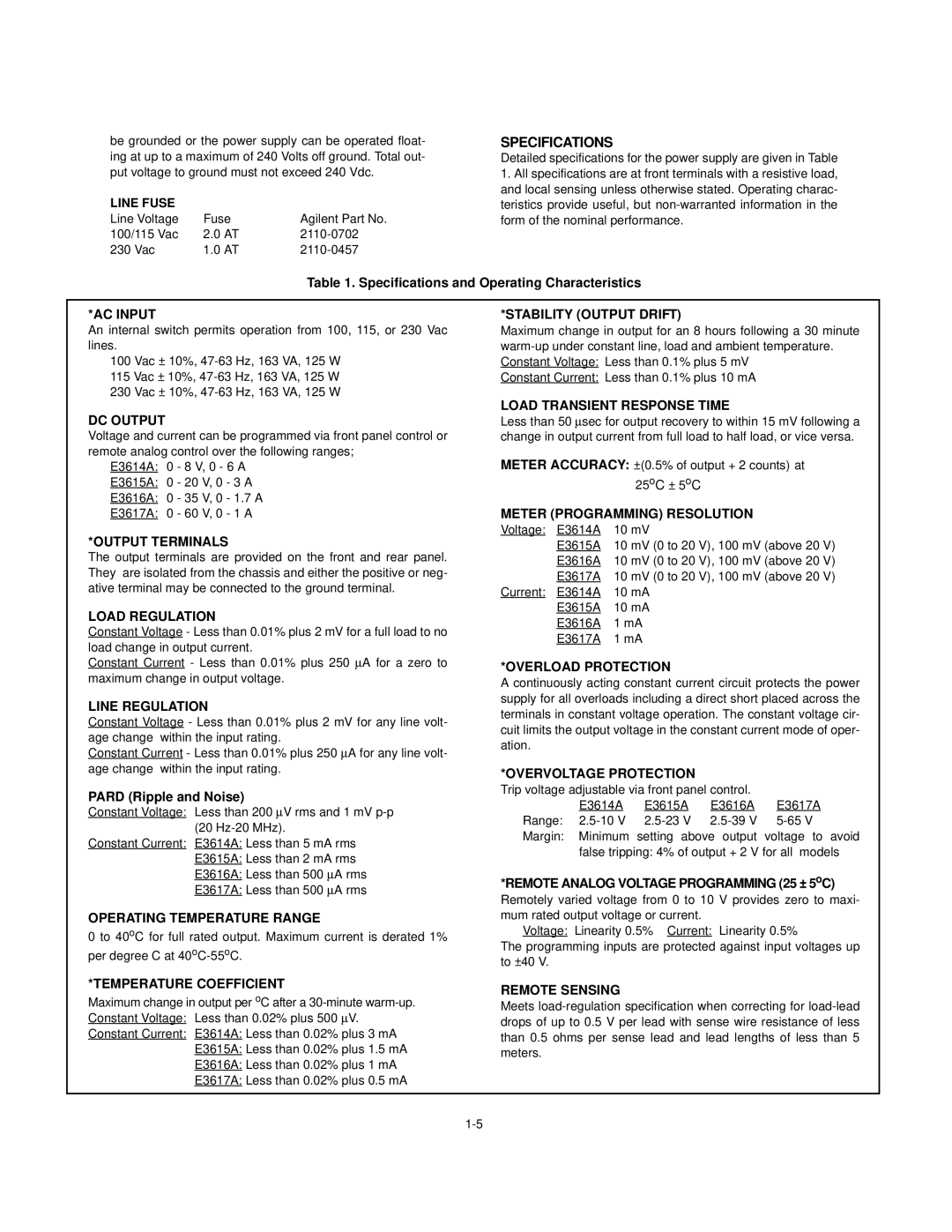
SPECIFICATIONS
Detailed specifications for the power supply are given in Table
1.All specifications are at front terminals with a resistive load, and local sensing unless otherwise stated. Operating charac- teristics provide useful, but
Table 1. Specifications and Operating Characteristics
*AC INPUT
An internal switch permits operation from 100, 115, or 230 Vac lines.
100Vac ± 10%,
115Vac ± 10%,
230Vac ± 10%,
*STABILITY (OUTPUT DRIFT)
Maximum change in output for an 8 hours following a 30 minute
Constant Current: Less than 0.1% plus 10 mA
DC OUTPUT
Voltage and current can be programmed via front panel control or remote analog control over the following ranges;
E3614A: 0 - 8 V, 0 - 6 A
E3615A: 0 - 20 V, 0 - 3 A
E3616A: 0 - 35 V, 0 - 1.7 A
E3617A: 0 - 60 V, 0 - 1 A
*OUTPUT TERMINALS
The output terminals are provided on the front and rear panel. They are isolated from the chassis and either the positive or neg- ative terminal may be connected to the ground terminal.
LOAD REGULATION
Constant Voltage - Less than 0.01% plus 2 mV for a full load to no load change in output current.
Constant Current - Less than 0.01% plus 250 μA for a zero to maximum change in output voltage.
LINE REGULATION
Constant Voltage - Less than 0.01% plus 2 mV for any line volt- age change within the input rating.
Constant Current - Less than 0.01% plus 250 μA for any line volt- age change within the input rating.
PARD (Ripple and Noise)
Constant Voltage: Less than 200 μV rms and 1 mV
(20
Constant Current: E3614A: Less than 5 mA rms E3615A: Less than 2 mA rms E3616A: Less than 500 μA rms E3617A: Less than 500 μA rms
OPERATING TEMPERATURE RANGE
0 to 40oC for full rated output. Maximum current is derated 1% per degree C at
LOAD TRANSIENT RESPONSE TIME
Less than 50 μsec for output recovery to within 15 mV following a change in output current from full load to half load, or vice versa.
METER ACCURACY: ±(0.5% of output + 2 counts)Bat
|
| 25oC ± 5oC |
METER (PROGRAMMING) RESOLUTION | ||
Voltage: | E3614A | 10 mV |
| E3615A 10 mV (0 to 20 V), 100 mV (above 20 V) | |
| E3616A 10 mV (0 to 20 V), 100 mV (above 20 V) | |
| E3617A 10 mV (0 to 20 V), 100 mV (above 20 V) | |
Current: | E3614A | 10 mA |
| E3615A | 10 mA |
| E3616A | 1 mA |
| E3617A | 1 mA |
*OVERLOAD PROTECTION
A continuously acting constant current circuit protects the power supply for all overloads including a direct short placed across the terminals in constant voltage operation. The constant voltage cir- cuit limits the output voltage in the constant current mode of oper- ation.
*OVERVOLTAGE PROTECTION
Trip voltage adjustable via front panel control.
E3614A E3615A E3616A E3617A Range:
false tripping: 4% of output + 2 V for all models
*REMOTE ANALOG VOLTAGE PROGRAMMING (25 ± 5oC)
Remotely varied voltage from 0 to 10 V provides zero to maxi- mum rated output voltage or current.
Voltage: Linearity 0.5% Current: Linearity 0.5%
The programming inputs are protected against input voltages up to ±40 V.
*TEMPERATURE COEFFICIENT
Maximum change in output per oC after a
Constant Current: E3614A: Less than 0.02% plus 3 mA E3615A: Less than 0.02% plus 1.5 mA E3616A: Less than 0.02% plus 1 mA E3617A: Less than 0.02% plus 0.5 mA
REMOTE SENSING
Meets
