Setting Voltage and Current. Turn the slave unit's CURRENT control fully clockwise. Adjust the master unit's controls to set the desired output voltage and current. The master supply operates in a completely normal fashion and may be set up for either con- stant voltage or constant current operation as required. Verify that the slave is in CV operation.
For
Io = Im + Is = 2Im
where Im = master unit's output current Is = slave unit's output current
Proportional currents from
MASTER POWER SUPPLY |
|
|
|
|
|
|
|
|
|
|
| |||
MASTER |
| LOCAL |
|
| + | _ |
| + | _ | + | _ |
|
| |
M/S 1 | M/S 2 | CV | CC | SENSE | +S |
| OUT | CV |
|
| CC VREF A1 A2 | A3 | A4 A5 | |
SLAVE |
| REMOTE |
|
|
| |||||||||
|
|
|
|
|
|
|
|
|
|
| ||||
|
|
|
|
|
|
|
| LOAD |
|
|
|
|
|
|
SLAVE POWER SUPPLY |
|
|
|
|
|
|
|
|
|
|
|
| ||
MASTER |
| LOCAL |
|
| + | _ |
| + | _ | + | _ |
|
| |
M/S 1 | M/S 2 | CV | CC | SENSE | +S |
| OUT | CV |
|
| CC VREF A1 A2 | A3 | A4 A5 | |
SLAVE |
| REMOTE |
|
|
| |||||||||
|
|
|
|
|
|
|
|
|
|
| ||||
Figure 9. Auto-Parallel Operation of Two Supplies
Overvoltage Protection. Adjust the desired OVP shutdown limit using the master unit's OVP Adjust control. Set the slave units' OVP limits above the master's. When a
Remote Sensing. To remote sense with
Remote Analog Voltage Programming. To remote program with
gramming according to the remote-programming instructions.
MASTER POWER SUPPLY |
|
|
| _ |
|
| _ | + _ |
|
|
| ||
MASTER |
| LOCAL |
|
| + |
| + |
|
|
| |||
M/S 1 M/S 2 | CV | CC | SENSE | +S | OUT |
| CV |
| CC VREF A1 A2 | A3 | A4 | A5 | |
SLAVE |
|
|
|
|
| ||||||||
| REMOTE |
|
|
|
|
|
|
|
|
|
|
| |
|
|
|
|
|
|
| LOAD |
|
|
|
|
|
|
SLAVE POWER SUPPLY |
|
|
| _ |
|
| _ | + _ |
|
|
| ||
MASTER |
| LOCAL |
|
| + |
| + |
|
|
| |||
M/S 1 M/S 2 | CV | CC | SENSE | +S | OUT |
| CV |
| CC VREF A1 A2 | A3 | A4 | A5 | |
SLAVE |
|
|
|
|
| ||||||||
| REMOTE |
|
|
|
|
|
|
|
|
|
|
| |
SLAVE POWER SUPPLY |
|
|
| _ |
|
| _ | + _ |
|
|
| ||
MASTER |
| LOCAL |
|
| + |
| + |
|
|
| |||
M/S 1 M/S 2 | CV | CC | SENSE | +S | OUT |
| CV |
| CC VREF A1 A2 | A3 | A4 | A5 | |
SLAVE |
|
|
|
|
| ||||||||
| REMOTE |
|
|
|
|
|
|
|
|
|
|
| |
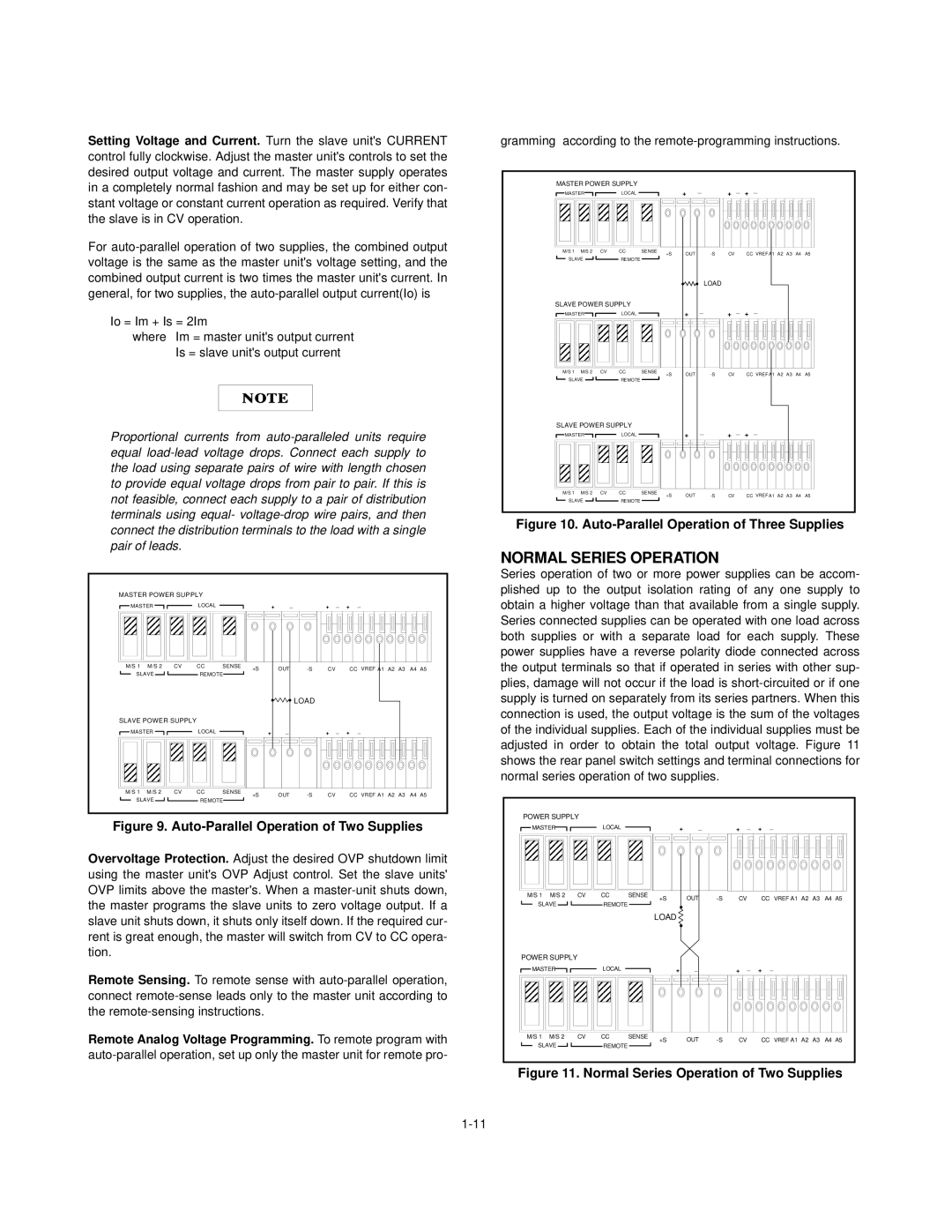
Figure 10. Auto-Parallel Operation of Three Supplies
NORMAL SERIES OPERATION
Series operation of two or more power supplies can be accom- plished up to the output isolation rating of any one supply to obtain a higher voltage than that available from a single supply. Series connected supplies can be operated with one load across both supplies or with a separate load for each supply. These power supplies have a reverse polarity diode connected across the output terminals so that if operated in series with other sup- plies, damage will not occur if the load is
POWER SUPPLY |
|
|
|
|
|
|
|
|
|
| ||
MASTER |
| LOCAL |
| + | _ |
| + | _ | + | _ |
| |
M/S 1 | M/S 2 | CV | CC | SENSE | +S | OUT | CV |
| CC | VREF A1 A2 A3 | A4 A5 | |
SLAVE |
| REMOTE |
|
| ||||||||
|
|
|
|
|
|
|
|
|
| |||
|
|
|
|
| LOAD |
|
|
|
|
|
|
|
POWER SUPPLY |
|
|
|
|
|
|
|
|
|
|
| |
MASTER |
| LOCAL |
| + | _ |
| + | _ | + | _ |
| |
M/S 1 | M/S 2 | CV | CC | SENSE | +S | OUT | CV |
| CC | VREF A1 A2 A3 | A4 A5 | |
SLAVE |
| REMOTE |
|
| ||||||||
|
|
|
|
|
|
|
|
|
| |||